12.7/22kV Three Core Individual Screened & PVC/SWA/PVC Sheathed (Cu Conductor)
Application
These cables are designed to be used for the supply of electrical energy in fixed applications up to the rated voltages at a nominal power frequency between 49Hz and 61Hz., they are suitable for use in distribution installation, electrical power station , they are applied for installation, outdoors, underground where subject to mechanical damage.
Standard
AS/NZS 1429.1
Cable Construction
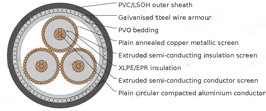
CONDUCTOR: Plain circular compacted copper to AS/NZS1125 Maximum Continuous Operating Temperature: 90°C
CONDUCTOR SCREEN: Extruded semi-conducting compound, bonded to the insulation and applied in the same operation as the insulation
INSULATION: Cross Linked Polyethylene (XLPE) – standard Ethylene Propylene Rubber (EPR) – alternative
INSULATION SCREEN: Extruded semi-conducting compound
METALLIC SCREEN: Plain annealed copper wire: 10kA for nominal 1 second(HEAVY DUTY)
BEDDING: PVC
ARMOURING: Galvanised steel wires
SHEATH: Black 5V-90 polyvinyl chloride (PVC) – standard
Orange 5V-90 PVC inner plus black high density polyethylene (HDPE) outer – alternative Low smoke zero halogen (LSOH) – alternative
Technical Characteristics
NOMINAL CONDUCTOR AREA | MAXIMUM CONDUCTOR DC RESISTANCE AT 20°C | COND. AC RESISTANCE AT 50HZ AND 90°C | INDUCTIVE REACTANCE AT 50HZ | INSULATION RESISTANCE AT 20°C | CONDUCTOR TO SCREEN CAPACI TANCE | CHARGING CURRENT PER PHASE | DIELE CTRIC LOSS PER PHRASE | MAXI MUM DIAELE CTRIC STRESS | SCREENDC RESISTANCE AT 20°C | ARMOURDC RESISTANCE AT 20°C | ZERO SEQUENCE RESISTANCE AT 20°C | ZERO SEQ. REACT. AT 50HZ |
|---|---|---|---|---|---|---|---|---|---|---|---|---|
MM2 | OHM/KM | OHM/KM | OHM/KM | MEGOHM. KM | ΜF X KM | A X KM | W X KM | KV X MM | OHM/KM | OHM/KM | OHM/KM | OHM/KM |
0.524 | 0.668 | 0.141 | 16000 | 0.156 | 0.622 | 31.6 | 3.63 | 0.531 | 0.487 | 1.29 | 0.0923 | |
0.387 | 0.494 | 0.134 | 14000 | 0.171 | 0.682 | 34.7 | 3.48 | 0.367 | 0.465 | 1 | 0.0858 | |
0.268 | 0.342 | 0.127 | 13000 | 0.192 | 0.765 | 38.9 | 3.31 | 0.265 | 0.438 | 0.763 | 0.0786 | |
0.193 | 0.247 | 0.117 | 11000 | 0.216 | 0.862 | 43.8 | 3.16 | 0.265 | 0.408 | 0.675 | 0.0693 | |
0.153 | 0.196 | 0.112 | 10000 | 0.236 | 0.942 | 47.8 | 3.07 | 0.265 | 0.302 | 0.577 | 0.0648 | |
0.124 | 0.16 | 0.109 | 9500 | 0.254 | 1.01 | 51.5 | 3 | 0.266 | 0.288 | 0.54 | 0.0615 | |
0.0991 | 0.128 | 0.105 | 8800 | 0.274 | 1.09 | 55.6 | 2.93 | 0.266 | 0.276 | 0.506 | 0.0582 | |
0.0754 | 0.0981 | 0.101 | 7900 | 0.305 | 1.22 | 61.8 | 2.85 | 0.265 | 0.257 | 0.468 | 0.0542 | |
0.0601 | 0.0792 | 0.0988 | 7200 | 0.334 | 1.33 | 67.8 | 2.79 | 0.265 | 0.241 | 0.44 | 0.0519 | |
0.047 | 0.0633 | 0.0944 | 6500 | 0.371 | 1.48 | 75.1 | 2.73 | 0.265 | 0.224 | 0.413 | 0.0477 | |
0.0373 | 0.0518 | 0.0915 | 5900 | 0.407 | 1.62 | 82.4 | 2.69 | 0.265 | 0.209 | 0.39 | 0.045 |
Cable Parameter
SECTIONAL AREA OF CONDUCTOR | NOM. CONDUCTOR DIAMETER | NOM. INSULATION THICKNESS | NOM. DIAMETE OVER INSULATION | SCREEN AREA ON CORES | NO. AND DIAMTER OF SCREENED WIRES | NOM. DIAMETE OVER SCREENED WIRES | NOM. DIAMETE OVER BEDDING | NOM. DIAMETE OF ARMOUR | NOM. DIAMETE OVER ARMOUR | NOM. OVERALL DIAMETER | ? APPROX. MASS |
|---|---|---|---|---|---|---|---|---|---|---|---|
MM2 | MM | MM | MM | MM2 | NO X MM | MM | MM | MM | MM | MM | KG/100M |
35 | 6.8 | 5.5 | 19.1 | 34 | 20 x 0.85 | 22.4 | 52.1 | 2.5 | 57.1 | 63.2 | 610 |
50 | 8 | 5.5 | 20.3 | 49.4 | 29 x 0.85 | 23.6 | 54.8 | 2.5 | 59.8 | 66 | 685 |
70 | 9.6 | 5.5 | 21.9 | 68.1 | 40 x 0.85 | 25.2 | 58.5 | 2.5 | 63.5 | 70.1 | 810 |
95 | 11.5 | 5.5 | 23.8 | 68.1 | 40 x 0.85 | 27.1 | 62.6 | 2.5 | 67.6 | 74.4 | 935 |
120 | 13.1 | 5.5 | 25.3 | 68.1 | 40 x 0.85 | 28.6 | 66.3 | 3.15 | 72.6 | 79.6 | 1140 |
150 | 14.5 | 5.5 | 26.8 | 68.1 | 40 x 0.85 | 30.1 | 69.6 | 3.15 | 75.9 | 83.1 | 1270 |
185 | 16.1 | 5.5 | 28.4 | 68.1 | 40 x 0.85 | 31.7 | 73 | 3.15 | 79.3 | 87 | 1400 |
240 | 18.5 | 5.5 | 30.8 | 68.1 | 40 x 0.85 | 34.1 | 78.5 | 3.15 | 84.8 | 92.6 | 1640 |
300 | 20.7 | 5.5 | 33.2 | 68.1 | 40 x 0.85 | 36.7 | 84.2 | 3.15 | 90.5 | 98.8 | 1900 |
400 | 23.6 | 5.5 | 36.1 | 68.1 | 40 x 0.85 | 39.6 | 90.7 | 3.15 | 97 | 105.6 | 2260 |
500 | 26.5 | 5.5 | 39 | 68.1 | 40 x 0.85 | 42.5 | 97.1 | 3.15 | 103.4 | 112.5 | 2640 |