19/33kV Three Core Individual Screened & PVC/SWA/PVC Sheathed (Cu Conductor)
Application
These cables are designed to be used for the supply of electrical energy in fixed applications up to the rated voltages at a nominal power frequency between 49Hz and 61Hz., they are suitable for use in distribution installation, electrical power station , they are applied for installation, outdoors, underground where subject to mechanical damage.
Standard
AS/NZS 1429.1
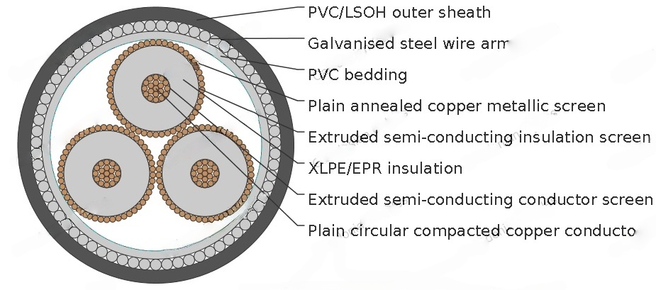
Cable Construction
CONDUCTOR: Plain circular compacted copper to AS/NZS1125 Maximum Continuous Operating Temperature: 90°C
CONDUCTOR SCREEN: Extruded semi-conducting compound, bonded to the insulation and applied in the same operation as the insulation
INSULATION: Cross Linked Polyethylene (XLPE) – standard Ethylene Propylene Rubber (EPR) – alternative
INSULATION SCREEN: Extruded semi-conducting compound
METALLIC SCREEN: Plain annealed copper wire: 10kA for nominal 1 second(HEAVY DUTY)
BEDDING: PVC
ARMOURING: Galvanised steel wires
SHEATH: Black 5V-90 polyvinyl chloride (PVC) – standard
Orange 5V-90 PVC inner plus black high density polyethylene (HDPE) outer – alternative Low smoke zero halogen (LSOH) – alternative
Technical Characteristics
NOMINAL CONDUCTOR AREA | MAXIMUM CONDUCTOR DC RESISTANCE AT 20°C | COND. AC RESISTANCE AT 50HZ AND 90°C | INDUCTIVE REACTANCE AT 50HZ | INSULATION RESISTANCE AT 20°C | CONDUCTOR TO SCREEN CAPACITANCE | CHARGING CURRENT PER PHASE | DIELE CTRIC LOSS PER PHR ASE | MAXIMUM DIAELECTRIC STRESS | SCREE NDC RESIS TANCE AT 20°C | ARMOURDC RESISTANCE AT 20°C | ZERO SEQUENCE RESISTANCE AT 20°C | ZERO SEQ. REACT. AT 50HZ |
|---|---|---|---|---|---|---|---|---|---|---|---|---|
MM | OHM/KM | OHM/KM | OHM/KM | MEGOHM. KM | ΜF X KM | A X KM | W? X KM | KV X MM | OHM /KM | OHM/KM | OHM/KM | OHM/KM |
0.387 | 0.494 | 0.147 | 18000 | 0.133 | 0.796 | 60.5 | 4.05 | 0.366 | 0.302 | 0.884 | 0.0988 | |
0.268 | 0.342 | 0.139 | 16000 | 0.148 | 0.883 | 67.1 | 3.82 | 0.265 | 0.288 | 0.682 | 0.0909 | |
0.193 | 0.247 | 0.128 | 15000 | 0.165 | 0.984 | 74.8 | 3.61 | 0.265 | 0.272 | 0.596 | 0.0807 | |
0.153 | 0.196 | 0.123 | 14000 | 0.179 | 1.07 | 81.1 | 3.48 | 0.265 | 0.261 | 0.548 | 0.0757 | |
0.124 | 0.159 | 0.12 | 13000 | 0.191 | 1.14 | 86.8 | 3.38 | 0.266 | 0.247 | 0.509 | 0.0722 | |
0.0991 | 0.128 | 0.116 | 12000 | 0.205 | 1.23 | 93.2 | 3.29 | 0.266 | 0.238 | 0.476 | 0.0685 | |
0.0754 | 0.0978 | 0.111 | 11000 | 0.227 | 1.35 | 103 | 3.17 | 0.265 | 0.224 | 0.441 | 0.0637 | |
0.0601 | 0.0788 | 0.107 | 9800 | 0.247 | 1.48 | 112 | 3.09 | 0.266 | 0.211 | 0.415 | 0.0605 | |
0.047 | 0.0628 | 0.102 | 8900 | 0.272 | 1.62 | 123 | 3 | 0.266 | 0.198 | 0.389 | 0.0557 | |
0.0373 | 0.0513 | 0.099 | 8100 | 0.297 | 1.77 | 135 | 2.93 | 0.265 | 0.215 | 0.395 | 0.0524 |
Cable Parameter
SECTIONAL AREA OF CONDUCTOR | NOM. CONDUCTOR DIAMETER | NOM. INSULATION THICKNESS | NOM. DIAMETE OVER INSULATION | SCREEN AREA ON CORES | NO. AND DIAMTER OF SCREENED WIRES | NOM. DIAMETE OVER SCREENED WIRES | NOM. DIAMETE OVER BEDDING | NOM. DIAMETE OF ARMOUR | NOM. DIAMETE OVER ARMOUR | NOM. OVERALL DIAMETER | APPROX. MASS |
|---|---|---|---|---|---|---|---|---|---|---|---|
MM2 | MM | MM | MM | MM2 | NO X MM | MM | MM | MM | MM | MM | KG/100M |
50 | 8 | 8 | 25.5 | 49.4 | 29 x 0.85 | 28.8 | 66.5 | 3.15 | 72.8 | 80.1 | 950 |
70 | 9.6 | 8 | 27.1 | 68.1 | 40 x 0.85 | 30.4 | 70.2 | 3.15 | 76.5 | 83.9 | 1080 |
95 | 11.5 | 8 | 29 | 68.1 | 40 x 0.85 | 32.3 | 74.2 | 3.15 | 80.5 | 88.2 | 1220 |
120 | 13.1 | 8 | 30.6 | 68.1 | 40 x 0.85 | 33.9 | 78 | 3.15 | 84.3 | 92.1 | 1340 |
150 | 14.5 | 8 | 32 | 68.1 | 40 x 0.85 | 35.5 | 81.7 | 3.15 | 88 | 96 | 1490 |
185 | 16.1 | 8 | 33.6 | 68.1 | 40 x 0.85 | 37.1 | 85.2 | 3.15 | 91.5 | 99.9 | 1630 |
240 | 18.5 | 8 | 36 | 68.1 | 40 x 0.85 | 39.5 | 90.6 | 3.15 | 96.9 | 105.6 | 1880 |
300 | 20.7 | 8 | 38.4 | 68.1 | 40 x 0.85 | 41.9 | 95.9 | 3.15 | 102.2 | 111.3 | 2140 |
400 | 23.6 | 8 | 41.3 | 68.1 | 40 x 0.85 | 44.8 | 102.4 | 3.15 | 108.7 | 118.1 | 2510 |
500 | 26.5 | 8 | 44.2 | 68.1 | 40 x 0.85 | 47.7 | 109 | 3.15 | 115.3 | 125.2 | 2900 |