Anhui Feichun Special Cable Co.,Ltd Li.wang@feichuncables.com

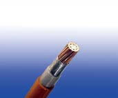
450/750V Mica+XLPE Insulated, LSZH Sheathed Power Cables to BS 7211 (Single Core)
Unveiling the Powerhouse: 450/750V Mica+XLPE Insulated, LSZH Sheathed Power Cables to BS 7211
450/750V Mica+XLPE Insulated, LSZH Sheathed Power Cables to BS 7211 (Single Core)
FFX300 07mRZ1-U/R (CU/MGT+XLPE/LSZH 450/750V Class 1/2)
APPLICATION
The cables are mainly used in power stations, mass transit underground passenger systems, airports, petrochemical plants, hotels, hospitals and high-rise buildings.
STANDARDS
Basic design adapted from BS 7211:2012
FIRE PERFORMANCE
Circuit Integrity | IEC 60331-21; BS 6387 |
Flame Retardance (Single vertical wire or cable test) | IEC 60332-1-2; EN 60332-1-2 |
Reduced Fire Propagation (Vertically-mounted bundled wires & cables test) | IEC 60332-3-24; EN 60332-3-24 |
Halogen free | IEC 60754-1; EN 50267-2-1 |
No Corrosive Gas Emission | IEC60754-2; EN 50267-2-2 |
Minimum Smoke Emission | IEC 61034-2; EN 61034-2 |
VOLTAGE RATING
450/750V
CABLE CONSTRUCTION
Conductor : Annealed copper conductor, solid or stranded according to BS EN 60228 class 1 or class 2.
Fire Barrier : Mica glass tape.
Insulation : XLPE type GP 8 according to BS 7655-1.3. Crosslinked polyolefin material type EI 5 according to EN 50363-5 can be offered as option.
CPC (Circuit Protective Conductor) : Uninsulated copper conductor.
Outer Sheath : Extruded LSZH type LTS 4 according to BS 7655-6.1.
Outer Sheath Option : UV resistance, hydrocarbon resistance, oil resistance, anti-rodent and anti-termite properties can be offered as option.
COLOUR CODE
Insulation Colour : Brown or blue.
Sheath Colour: White; other colours can be offered upon request.
PHYSICAL AND THERMAL PROPERTIES
Maximum temperature range during operation : 90°C
Maximum short circuit temperature (5 Seconds) : 250°C
Minimum bending radius :
OD<8mm : 4 × Overall Diameter
8mm≤OD≤12mm : 5 × Overall Diameter
OD>12mm : 6 × Overall Diameter
CONSTRUCTION PARAMETERS
Conductor | FFX300 07mRZ1-U/R | |||||
|---|---|---|---|---|---|---|
No. of Cores × Cross-sectional Area | Conductor Class | Nominal Insulation Thickness | Nominal Sheath Thickness | Min. Overall Diameter | Max. Overall Diameter | Approx. Weight |
No.×mm² |
| mm | mm | mm | mm | kg/km |
1×1.0 | 1 | 0.7 | 0.8 | 4.9 | 5.8 | 30 |
1×1.5 | 1 | 0.7 | 0.8 | 5.2 | 6.0 | 38 |
1×2.5 | 1 | 0.7 | 0.8 | 5.6 | 6.5 | 51 |
1×4 | 1 | 0.7 | 0.8 | 6.2 | 7.3 | 70 |
1×6 | 1 | 0.7 | 0.8 | 6.7 | 7.8 | 95 |
1×1.0 | 2 | 0.7 | 0.8 | 5.0 | 5.9 | 35 |
1×1.5 | 2 | 0.7 | 0.8 | 5.3 | 6.2 | 43 |
1×2.5 | 2 | 0.7 | 0.8 | 5.7 | 6.6 | 56 |
1×4 | 2 | 0.7 | 0.9 | 6.3 | 7.4 | 77 |
1×6 | 2 | 0.7 | 0.9 | 6.9 | 8.1 | 104 |
1×10 | 2 | 0.7 | 0.9 | 7.7 | 9.1 | 147 |
1×16 | 2 | 0.7 | 0.9 | 8.6 | 10.2 | 211 |
1×25 | 2 | 0.9 | 1.0 | 10.4 | 12.4 | 325 |
1×35 | 2 | 0.9 | 1.1 | 11.6 | 13.8 | 489 |
ELECTRICAL PROPERTIES
Conductor operating temperature : 90°C
Ambient temperature : 30°C
Current-Carrying Capacities (Amp) according to BS 7671:2008 table 4E1A
Conductor cross-sectional area | Ref. Method A (enclosed in conduit in thermally insulating wall etc.) | Ref. Method B (enclosed in conduit on a wall or in trunking etc.) | Ref. Method C (clipped direct) | Ref. Method F (in free air or on a perforated cable tray, horizontal or vertical etc) Touching | Ref. Method G (in free air) Spaced by one cable diameter | ||||||
|---|---|---|---|---|---|---|---|---|---|---|---|
2 cables, single-phase a.c. or d.c. | 3 or 4 cables, three-phase a.c. | 2 cables, single-phase a.c. or d.c | 3 or 4 cables, three-phase a.c. | 2 cables, single-phase a.c. or d.c. flat and touching | 3 or 4 cables, three-phase a.c. flat and touching or trefoil | 2 cables, single-phase a.c. or d.c. flat | 3 cables, three-phase a.c. flat | 3 cables, three-phase a.c. trefoil | 2 cables, single-phase a.c. or d.c. or 3 cables three-phase a.c. flat | ||
Horizontal | Vertical | ||||||||||
1 | 2 | 3 | 4 | 5 | 6 | 7 | 8 | 9 | 10 | 11 | 12 |
mm² | A | A | A | A | A | A | A | A | A | A | A |
1.0 | 14 | 13 | 17 | 15 | 19 | 17.5 | - | - | - | - | - |
1.5 | 19 | 17 | 23 | 20 | 25 | 23 | - | - | - | - | - |
2.5 | 26 | 23 | 31 | 28 | 34 | 31 | - | - | - | - | - |
4 | 35 | 31 | 42 | 37 | 46 | 41 | - | - | - | - | - |
6 | 45 | 40 | 54 | 48 | 59 | 54 | - | - | - | - | - |
10 | 61 | 54 | 75 | 66 | 81 | 74 | - | - | - | - | - |
16 | 81 | 73 | 100 | 88 | 109 | 99 | - | - | - | - | - |
25 | 106 | 95 | 133 | 117 | 143 | 130 | 161 | 141 | 135 | 182 | 161 |
35 | 131 | 117 | 164 | 144 | 176 | 161 | 200 | 176 | 169 | 226 | 201 |
Conductor cross-sectional area | 2 cables d.c. | 2 cables, single-phase a.c. | 3 or 4 cables, three-phase a.c. | |||||||||||||||||||
|---|---|---|---|---|---|---|---|---|---|---|---|---|---|---|---|---|---|---|---|---|---|---|
Ref. Methods A&B (enclosed in conduit or trunking) | Ref. Methods C, F&G (clipped direct, on trays or in free air) | Ref. Methods A&B (enclosed in conduit or trunking) | Ref. Methods C, F&G (clipped direct, on trays or in free air) | |||||||||||||||||||
Cables touching | Cables spaced* | Cables touching, Trefoil | Cables touching, flat | Cables spaced*, flat | ||||||||||||||||||
1 | 2 | 3 | 4 | 5 | 6 | 7 | 8 | 9 | ||||||||||||||
mm² | mV/A/m | mV/A/m | mV/A/m | mV/A/m | mV/A/m | mV/A/m | mV/A/m | mV/A/m | ||||||||||||||
1.0 | 46 | 46 | 46 | 46 | 40 | 40 | 40 | 40 | ||||||||||||||
1.5 | 31 | 31 | 31 | 31 | 27 | 27 | 27 | 27 | ||||||||||||||
2.5 | 19 | 19 | 19 | 19 | 16 | 16 | 16 | 16 | ||||||||||||||
4 | 12 | 12 | 12 | 12 | 10 | 10 | 10 | 10 | ||||||||||||||
6 | 7.9 | 7.9 | 7.9 | 7.9 | 6.8 | 6.8 | 6.8 | 6.8 | ||||||||||||||
10 | 4.7 | 4.7 | 4.7 | 4.7 | 4.0 | 4.0 | 4.0 | 4.0 | ||||||||||||||
16 | 2.9 | 2.9 | 2.9 | 2.9 | 2.5 | 2.5 | 2.5 | 2.5 | ||||||||||||||
|
| r | x | z | r | x | z | r | x | z | r | x | z | r | x | z | r | x | z | r | x | z |
25 | 1.85 | 1.85 | 0.31 | 1.90 | 1.85 | 0.190 | 1.85 | 1.85 | 0.28 | 1.85 | 1.60 | 0.27 | 1.65 | 1.60 | 0.165 | 1.60 | 1.60 | 0.190 | 1.60 | 1.60 | 0.27 | 1.65 |
35 | 1.35 | 1.35 | 0.29 | 1.35 | 1.35 | 0.180 | 1.35 | 1.35 | 0.27 | 1.35 | 1.15 | 0.25 | 1.15 | 1.15 | 0.155 | 1.15 | 1.15 | 0.180 | 1.15 | 1.15 | 0.26 | 1.20 |
Note: *Spacings larger than one cable diameter will result in a large voltage drop.
r = conductor resistance at operating temperature
x = reactance
z = impedance
Introduction to Fire-Resistant Power Cables
In the world of electrical engineering, safety, reliability, and performance are paramount. The 450/750V Mica+XLPE Insulated, Low Smoke Zero Halogen (LSZH) Sheathed Power Cables, designed to meet the British Standard BS 7211, stand out as a robust solution for critical applications. These single-core cables, often referred to as FFX300 07mRZ1-U/R, are engineered to deliver power while ensuring fire resistance, minimal smoke emission, and environmental safety. Their use in high-risk environments like power stations, hospitals, and mass transit systems makes them a vital component in modern infrastructure, particularly in regions like South Africa, where safety standards are increasingly stringent.
Standards Governing the Cables
The 450/750V Mica+XLPE Insulated, LSZH Sheathed Power Cables adhere to rigorous international and British standards, ensuring compliance with safety and performance requirements:
BS 7211:2012: The primary standard for these cables, specifying requirements for low-voltage, fire-resistant cables with LSZH sheathing.
IEC 60331-21 and BS 6387: Ensure circuit integrity during fire exposure, critical for maintaining power to essential systems like fire alarms and emergency lighting.
IEC 60332-1-2 and EN 60332-1-2: Test flame retardance for single cables, ensuring they resist fire spread.
IEC 60332-3-24 and EN 60332-3-24: Verify reduced fire propagation in bundled cable installations.
IEC 60754-1 and EN 50267-2-1: Confirm halogen-free properties, with HCl emissions below 0.5%, reducing toxicity risks.
IEC 60754-2 and EN 50267-2-2: Ensure no corrosive gas emissions, protecting equipment and people.
IEC 61034-2 and EN 61034-2: Guarantee minimal smoke emission, improving visibility and safety during fire incidents.
Usage Scenarios in South Africa
In South Africa, where rapid urbanization and infrastructure development are ongoing, these cables are critical in various applications:
Power Stations: Used in control circuits to maintain power supply integrity during emergencies.
Mass Transit Systems: Essential in underground metro systems, such as those in Johannesburg and Cape Town, where fire safety is critical.
Hospitals and High-Rise Buildings: Deployed in emergency lighting and fire alarm systems to ensure safe evacuation and operation during fires.
Petrochemical Plants: Their resistance to hydrocarbons and oils makes them suitable for South Africa’s growing energy sector.
Airports: Used in critical systems like runway lighting and control panels, ensuring operational continuity.
The cables’ LSZH properties are particularly valuable in South Africa, where building regulations increasingly emphasize fire safety and low toxicity in public spaces. Their ability to maintain circuit integrity under fire conditions aligns with the country’s push for safer infrastructure.
Benefits of Mica+XLPE Insulated, LSZH Sheathed Cables
Fire Resistance: The mica tape ensures circuit integrity, allowing critical systems to function during fires.
Low Smoke and Toxicity: LSZH sheathing reduces smoke and toxic gas emissions, enhancing safety in enclosed spaces.
Durability: XLPE insulation withstands high temperatures and mechanical stress, ensuring long-term reliability.
Versatility: Optional features like UV and hydrocarbon resistance make the cables adaptable to diverse environments.
Compliance: Adherence to international standards ensures global applicability and regulatory approval.
The 450/750V Mica+XLPE Insulated, LSZH Sheathed Power Cables to BS 7211 are a cornerstone of modern electrical infrastructure, particularly in safety-critical environments. Their robust construction, adherence to stringent standards, and adaptability to diverse applications make them indispensable in South Africa’s rapidly evolving urban and industrial landscape. From powering emergency systems in hospitals to ensuring safety in metro systems, these cables deliver unmatched reliability and safety. As South Africa continues to prioritize fire safety and sustainable infrastructure, these cables will play a pivotal role in shaping a safer future.

Email Address: Li.wang@feichuncables.com
© 2025. All rights reserved.


One-click to Quickly Contact
Products
Offshore & Marine Cable
XLPE Cable
Contact
Company
Location:
Building A Private Science and Technology Park, Hefei Economic and Technological Development Zone, Anhui Province, China
