Anhui Feichun Special Cable Co.,Ltd Email: Li.wang@feichuncables.com

AS/NZS 1802 Type 209 1.1kV–11kV Cable Guide: Composite Screened Heavy‑Duty EPR Mining Feeder Cable Flexible Power Cable for Pumps, Crushers and Mobile Equipment
AS/NZS 1802 Type 209 cable (1.1kV–11kV) is a heavy‑duty, composite screened trailing and feeder cable designed to AS/NZS 1802 standards, featuring EPR insulation, tinned copper conductors and an extensible central pilot core. This detailed guide covers engineering design principles, material selection science, performance benefits, full technical specifications, correct selection methods, and why Feichun Type 209 serves as a fully equivalent, cost‑effective alternative to premium brands. It is an essential reference for electrical engineers, procurement specialists and mine operators across South Africa, Australia and global mining sectors.
Li Wang
5/20/202621 min read
Introduction
In underground mining, open‑pit operations and heavy industrial environments, the choice of power cable directly impacts safety, operational continuity and total cost of ownership. Cables must withstand constant movement, heavy mechanical stress, moisture, chemical exposure and wide temperature fluctuations while maintaining reliable electrical performance. Among the range of cables developed specifically for these demanding conditions, AS/NZS 1802 Type 209 has become the established standard across Australia, New Zealand, South Africa and many other mining regions worldwide.
Type 209 is defined as a composite screened cable for general use, manufactured in accordance with AS/NZS 1802:2018 and supporting standards including AS/NZS 1125, AS/NZS 1972 and AS/NZS 5000.1. It covers voltage ratings from 1.1kV up to 11kV and features a distinctive construction: three power cores plus one central extensible pilot core, all protected by a composite screen and heavy‑duty elastomer sheath. This design is purpose‑built for feeder connections between transformers and gate‑end boxes, power supply to pumps, fans, crushers, conveyors and other mobile or semi‑fixed machinery, and can also be used as a direct replacement for older Type A or Type B feeder cables.
This guide provides a complete technical breakdown of Type 209 cable. It explains the engineering logic behind every layer, the science of material selection, the performance advantages that make it suitable for harsh environments, detailed specifications, guidance on selection and application, and practical insights for procurement. It also examines how Feichun’s equivalent version matches or exceeds the performance of premium brands while offering significant commercial benefits.
Standard Framework and Technical Definition
Understanding the AS/NZS 1802 Standard
The AS/NZS 1802 standard is the primary specification for reeling and trailing cables used in underground mining and heavy industry in Australia and New Zealand. The latest edition, AS/NZS 1802:2018, sets out requirements for construction, materials, dimensions, electrical performance, mechanical strength and fire behaviour. It is developed to ensure cables meet the strict safety and reliability needs of mining operations, where failure can lead to production loss, equipment damage or safety hazards.
This standard is supported by several related specifications that define individual components and test methods:
AS/NZS 1125: Conductors for electric cables – specifies materials, stranding and dimensional tolerances.
AS/NZS 1972: Elastomer insulation and sheathing compounds – defines performance requirements for rubber‑based materials.
AS/NZS 3808: Methods of test for electric cables under fire conditions – covers flame retardance and fire resistance.
AS/NZS 5000.1: Electric cables – general requirements.
Within the AS/NZS 1802 classification system, cables are grouped by design and intended use. Type 209 occupies a key position between general‑purpose cables (such as Type A and Type B) and high‑cycle reeling cables (such as Type 275). It is engineered for applications where cables are moved or trailed regularly but not subjected to continuous high‑speed reeling onto drums. This makes it the most widely used general‑purpose feeder and trailing cable in the region.
Core Features of Type 209
The official definition of Type 209 describes it as a “composite screened cable with a single extensible pilot core”. This simple description encapsulates three defining characteristics that shape its performance:
Composite screened cores: Each power core is individually screened, and the overall assembly is protected by a combined screen layer that serves both electrical and mechanical functions.
3‑phase power plus pilot core: The standard configuration is three power‑carrying conductors and one central pilot conductor. The pilot core is used for control, monitoring, interlocking or earth‑fault protection, a critical safety requirement in mining.
Extensible pilot design: The central pilot core is manufactured slightly longer than the power cores. When the cable is subjected to tension, the pilot core stretches first, absorbing mechanical load and preventing damage to the power conductors.
Type 209 is available in four voltage classes to match different system requirements:
Type 209.1: 1.1/1.1 kV
Type 209.3: 3.3/3.3 kV
Type 209.6: 6.6/6.6 kV
Type 209.11: 11/11 kV
Each voltage class shares the same fundamental design philosophy but differs in insulation thickness, screening details and dimensional specifications to handle the increased electrical stress at higher voltages.
Engineering Principles and Layer‑by‑Layer Design
Every component in Type 209 cable is designed with a specific function, and the interaction between layers creates a system that balances electrical safety, mechanical durability and environmental resistance. The construction follows a logical progression from the centre outwards: central pilot core → three phase power cores → separator/bedding layer → composite screen → inner protection → outer sheath.
Conductor System: Conductivity, Flexibility and Durability
The heart of any power cable is the conductor, and Type 209 uses tinned annealed stranded copper, manufactured to AS/NZS 1125.
Material choice: Copper is selected for its high electrical conductivity (minimum 98% IACS), excellent ductility and stable mechanical properties. Unlike aluminium, copper maintains low contact resistance over time and resists fatigue under repeated bending.
Tinning: Each individual wire is coated with a thin layer of tin. In mining environments, air often contains moisture, sulphur compounds and other corrosive agents. Bare copper would oxidise rapidly, increasing resistance and leading to overheating or connection failure. The tin coating acts as a barrier, preventing corrosion and ensuring consistent electrical performance for the life of the cable. It also improves solderability and makes terminations more reliable.
Annealing: The copper is fully annealed during manufacture. This heat‑treatment process softens the metal, relieves internal stresses and increases elongation to over 35%. An annealed conductor can withstand thousands of bending cycles without work‑hardening or breaking – a vital feature for cables that are moved or dragged regularly.
Stranding: Conductors are made from multiple fine wires stranded together in concentric layers. A solid conductor would be stiff and prone to fracture; stranding creates a flexible structure. The finer the strands, the more flexible the cable. Type 209 conductors use fine‑wire stranding to achieve a minimum bending radius of 6 × overall diameter when stationary and 8 × diameter when moving – significantly better than solid or coarse‑stranded alternatives.
Conductor sizes range from 6 mm² up to 300 mm², allowing selection to match load current, voltage drop and short‑circuit requirements.
Insulation System: Electric Field Control and Thermal Stability
Insulation is responsible for separating live conductors from each other and from earth, and its quality determines the voltage rating and long‑term reliability of the cable. Type 209 uses EPR (Ethylene Propylene Rubber), grade R‑EP‑90, an elastomeric compound specifically formulated for heavy‑duty power cables.
The engineering principles behind EPR insulation are based on its unique molecular structure and electrical properties:
Uniform electric field distribution: EPR has a consistent dielectric constant (approximately 2.3–2.5) and high dielectric strength (greater than 20 kV/mm). This means when voltage is applied, the electrical stress is distributed evenly throughout the insulation rather than concentrating at points or defects. This uniformity prevents partial discharge – a phenomenon where small electrical sparks inside insulation gradually erode material and eventually cause failure.
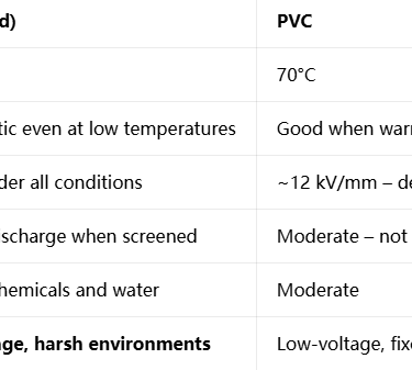
Temperature performance: EPR is rated for continuous operation at 90°C, with short‑circuit capability up to 250°C. Unlike thermoplastics such as PVC, which soften at high temperatures and become brittle when cold, EPR remains stable and elastic across a wide range. It retains flexibility down to -40°C, allowing installation and operation in both high‑temperature underground workings and cold surface environments.
Design variation by voltage:
1.1 kV cables: Insulation is applied directly over the conductor, with a protective textile tape wrap. This simpler design is cost‑effective while still meeting all performance requirements for low‑voltage systems.
3.3 kV, 6.6 kV and 11 kV cables: A triple‑layer construction is used: conductor screen → EPR insulation → insulation screen. Both screens are made of semiconductive material extruded simultaneously with the insulation. This design eliminates air gaps between the conductor and insulation, and between insulation and surrounding layers. By ensuring equal electrical potential across surfaces, it eliminates stress concentrations and completely controls partial discharge – essential for medium‑voltage reliability.
Separator and Bedding Layer
Between the insulated cores and the overall screen lies the separator or bedding layer. This component has two key functions:
Mechanical separation: It holds the cores in position, prevents them from rubbing against each other during bending or movement, and maintains the circular shape of the cable.
Electrical grading:
For 1.1 kV cables, polyester tape is used, providing mechanical stability without adding unnecessary complexity.
For 3.3 kV and above, a semiconductive PCP (Polychloroprene) compound is applied. This material equalises electrical potential around the core assembly, ensuring that any electrical field remains uniform and does not concentrate at irregularities.
Composite Screen: Dual‑Function Protection
One of the most distinctive features of Type 209 is its composite screen, constructed from tinned annealed copper wires braided together with polyester yarn. This is not simply a shield; it is a multi‑functional engineering solution.
Electrical role – Earth Continuity: The screen forms a continuous, low‑resistance path to earth. Under normal operation, it contains electrical fields and reduces electromagnetic interference. In the event of a fault, it carries earth‑fault current safely back to the protection system. The cross‑sectional area of the screen is designed to be at least 30% of the power conductor area, ensuring it can handle fault currents without damage. Resistance is kept below 0.003 Ω/m to ensure fast operation of protective devices.
Mechanical role – Tensile reinforcement: Copper braid alone is relatively fragile and can break under tension or repeated bending. By weaving high‑strength polyester yarn into the braid, the composite screen gains significant tensile strength. The polyester carries mechanical loads, protecting the copper wires from fatigue or fracture. This combination ensures the screen remains intact and effective throughout the cable’s service life.
Identification: Coloured tracers (red, white and blue) are woven into the screen over each phase core. This provides clear, permanent phase identification visible through the sheath, simplifying installation, testing and maintenance.
Central Pilot Core: Safety and Monitoring
Positioned right at the geometric centre of the cable is the pilot core. This location is chosen because the centre of a bent cable experiences the least mechanical stress, offering maximum protection to this critical element.
Construction: The pilot core is insulated with the same EPR compound as the power cores, ensuring it shares the same thermal and environmental properties.
Extensible design: As noted earlier, the pilot core is manufactured slightly longer than the power cores. When the cable is pulled or stretched, the pilot core elongates first, absorbing strain before the power cores are affected. This prevents control or monitoring signals from being lost due to mechanical damage.
Electrical specification: Resistance is strictly controlled: maximum 5.5 Ω/100 m for cables with power conductors up to 35 mm², and 3.0 Ω/100 m for larger sizes. This ensures signals remain clear and reliable over long distances.
Function: The pilot core is used for remote control, interlocking, earth‑fault indication or emergency stop systems. In mining, it is a mandatory safety feature, allowing operators to monitor cable integrity and disconnect power instantly if a fault is detected.
Outer Sheath: Ultimate Environmental Defence
The outermost layer is the heavy‑duty HD‑85 grade PCP sheath, sometimes also available in CSP (Chlorosulphonated Polyethylene) for extreme conditions. This layer provides the first line of defence against the environment and mechanical damage.
The formulation of the sheath compound is the result of extensive material science development to balance conflicting requirements:
Mechanical toughness: High tensile strength (>15 N/mm²), excellent tear resistance and high abrasion resistance. It can withstand being dragged over rock, crushed by heavy equipment or scraped against sharp edges without splitting or exposing underlying layers.
Flame performance: Compounded to be flame retardant and self‑extinguishing in accordance with AS/NZS 3808. It does not support combustion and releases low levels of non‑toxic smoke – critical for safety in confined underground spaces.
Chemical resistance: Resists degradation from mineral oils, greases, acids, alkalis, solvents and mine water. It also offers excellent resistance to ozone and ultraviolet radiation, making it suitable for both underground and direct outdoor exposure.
Temperature range: Rated for operation from -25°C up to +90°C, matching the insulation performance. Special low‑temperature versions can operate down to -40°C.
Sheath thickness increases with cable diameter and voltage class, ensuring that larger, heavier cables have proportionally greater protection. Reinforced sheaths with additional textile or wire layers are available as an option for applications involving extreme mechanical abuse.
Material Science: Why These Materials Were Selected
The performance of Type 209 is not just about design geometry; it comes from careful selection of materials based on their molecular properties and how they interact in service.
Conductors: Tinned Copper vs Alternatives
Aluminium conductors are common in some power applications, but they are unsuitable for Type 209. Aluminium has approximately 60% of the conductivity of copper, meaning larger sizes would be needed to carry the same current, increasing cable diameter and weight. More critically, aluminium forms a hard, non‑conductive oxide layer that makes reliable terminations difficult, especially in damp or corrosive environments. It also has poor fatigue resistance under bending.
Tinned copper solves all these issues. The tin coating is noble and stable, preventing oxidation while maintaining excellent conductivity. The combination of high‑purity copper and a protective tin layer delivers a conductor that is durable, reliable and easy to terminate.
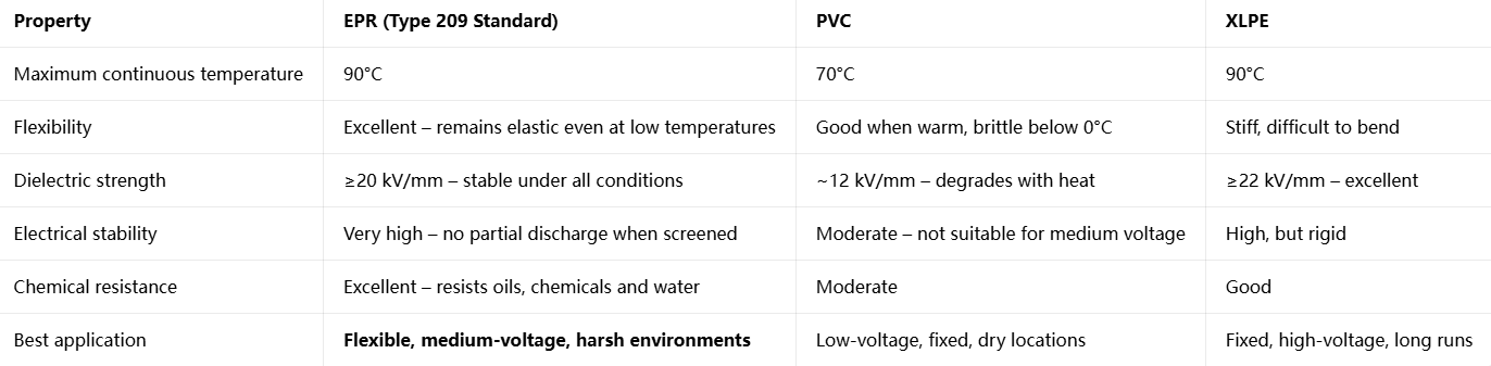
Insulation: EPR vs PVC vs XLPE
Three main insulation materials are used in power cables, each with distinct properties:
For Type 209’s requirements – flexibility, medium‑voltage capability, wide temperature range and resistance to mining environments – EPR is the only logical choice. Its amorphous molecular structure gives it permanent elasticity, unlike cross‑linked materials such as XLPE which become rigid once cured. EPR also has a much higher tolerance for moisture and chemical ingress than PVC, and it does not leach plasticisers or become brittle with age.
Sheath Compounds: PCP and CSP
Polychloroprene (PCP) is a synthetic rubber developed originally as an oil‑resistant alternative to natural rubber. Its molecular structure includes chlorine atoms that make it inherently flame‑retardant and resistant to oils, chemicals and ozone. When compounded with carbon black and antioxidants, it becomes an extremely robust material with excellent weathering properties.
Chlorosulphonated Polyethylene (CSP) offers even higher heat resistance and weathering performance, making it the choice for tropical or desert environments or applications where UV exposure is extreme. Both materials share the elastomeric nature that ensures the sheath remains bonded to the underlying layers and moves with the cable rather than cracking or separating.
Performance Advantages and Key Technical Data
The combination of careful design and high‑performance materials gives Type 209 a set of advantages that directly translate into better operational performance, longer life and lower total cost of ownership.
Core performance benefits
Electrical Safety: Zero partial discharge levels (<2pC) ensure long‑term insulation integrity. Tested to withstand AC voltages of 4 kV for 5 minutes (1.1 kV class) up to 24 kV for 5 minutes (11 kV class), plus impulse tests up to 75 kV. This provides a wide safety margin against system over‑voltages.
Mechanical Durability: Tensile strength exceeds 15 N/mm², allowing installation tension up to 15 N per mm² of conductor cross‑section without damage. Abrasion resistance is rated at over 5,000 cycles under standard test conditions – far exceeding typical operational demands. Impact resistance is rated at 20 Joules, meaning the cable can withstand heavy blows from falling rock or equipment without internal damage.
Environmental Stability: The complete construction is sealed and water‑blocking, achieving IP67 ingress protection. It can be submerged temporarily or continuously exposed to water without affecting performance. Resistance to UV radiation, ozone, acids, alkalis and mineral oils means the same cable can be used underground, in open‑pit mines or in industrial processing plants.
Fire Safety: Flame‑retardant properties meet AS/NZS 3808 requirements. If exposed to fire, the sheath does not support combustion, self‑extinguishes quickly and releases low levels of non‑toxic, low‑smoke emissions – a critical safety factor in confined spaces where smoke or toxic fumes could endanger personnel.
Service Life: Under normal operating conditions, Type 209 delivers 8 to 12 years of reliable service in underground environments and up to 15 to 20 years in surface applications. This extended life reduces replacement frequency, lowers maintenance costs and improves operational continuity.
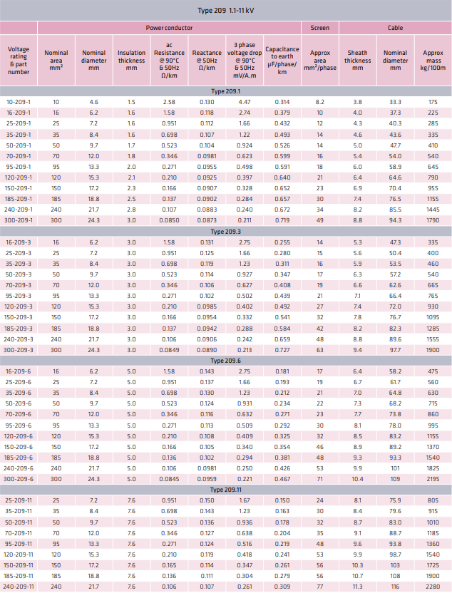
Complete Technical Specifications
The following tables outline the standard dimensional and performance data for Type 209, based on AS/NZS 1802 and manufacturer specifications. All values are nominal and subject to standard manufacturing tolerances.
Key Material and Performance Standards
Conductors: AS/NZS 1125, tinned annealed copper, class 2 or 5 stranded
Insulation: AS/NZS 1972, EPR type R‑EP‑90, 90°C rated
Screen: Composite tinned copper and polyester, minimum 30% of conductor cross‑section
Sheath: AS/NZS 1972, HD‑85 grade PCP or CSP, flame retardant
Temperature range: -25°C to +90°C operating; -40°C installation (with care)
Bending radius: 6 × OD (static), 8 × OD (moving)
Applications and Where to Use Type 209
Type 209 is designed as a general‑purpose heavy‑duty cable, and its versatility makes it suitable for a wide range of applications across mining and heavy industry. Understanding where it fits in relation to other cable types ensures correct selection and maximum service life.
Primary Application Areas
Underground Mining
This is the original and most common use for Type 209. It serves as the standard feeder cable connecting transformers to gate‑end switchboxes, and from there to individual items of machinery. Typical uses include:
Power supply to pumps, fans and ventilation equipment, where cables may be moved or re‑routed as workings advance.
Connection to crushers, conveyors and hoists, which operate continuously and require robust, reliable power.
Trailing supply to semi‑mobile equipment such as loaders, drills and continuous miners, where the cable follows the machine as it operates.
Replacement for older Type A or Type B cables, offering improved safety, longer life and better mechanical performance in the same installation footprint.
The presence of the pilot core makes Type 209 particularly valuable in underground mining, as it enables interlocking and earth‑fault protection systems that are mandatory for safety compliance.
Surface Mining and Quarrying
In open‑pit operations, conditions are less confined but often more exposed. Type 209 performs equally well here, with its UV‑stable, weather‑resistant sheath providing long life in direct sunlight, rain and extreme temperatures. Common applications include:
Power cables for mobile crushing and screening plants.
Supply to stackers, reclaimers and conveyor systems.
Connection to dewatering pumps and drilling rigs.
Temporary power distribution for construction and development work.
Heavy Industry and Processing
Beyond mining, Type 209 is widely used in industrial environments where reliability under harsh conditions is required:
Steel mills, smelters and foundries, where high temperatures, heavy mechanical loads and chemical exposure are common.
Ports and terminals, for mobile cranes, conveyors and loading equipment.
Water and wastewater treatment plants, for submersible pumps and process machinery.
Any application where a flexible, medium‑voltage cable with excellent environmental resistance is needed.
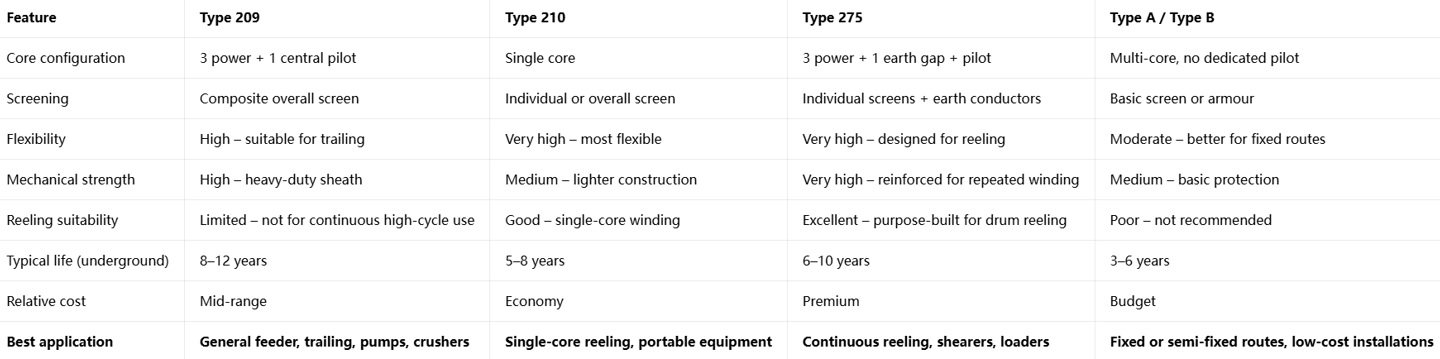
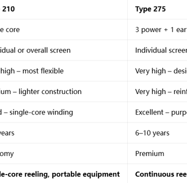
Comparison with Other AS/NZS 1802 Cable Types
Selecting the right cable means understanding how Type 209 compares to other options within the same standard. The following comparison highlights the differences in design and best use cases.
From this comparison, it becomes clear that Type 209 represents the optimal balance of performance, durability and cost for the majority of mining and industrial applications. It is flexible enough for regular movement, strong enough for heavy use, and protected sufficiently for long life in harsh environments. Only where continuous high‑cycle reeling is required does Type 275 become the better choice, while Type 210 is reserved for specific single‑core needs.
Selection Guide and Configuration Options
Choosing the correct Type 209 cable involves more than just matching voltage and size. A systematic approach ensures the selected cable meets all electrical, mechanical and environmental requirements, delivers full service life and represents the best value investment.
Step‑by‑Step Selection Process
Step 1: Determine Voltage Class
Select the voltage rating to match the system nominal voltage and insulation level. Never use a lower‑rated cable on a higher‑voltage system, as this will lead to rapid insulation failure.
1.1 kV class: Systems up to 1,000 V
3.3 kV class: Systems up to 3,300 V
6.6 kV class: Systems up to 6,600 V – most common medium‑voltage choice
11 kV class: Systems up to 11,000 V – main distribution and long feeders
Step 2: Calculate Conductor Size
Three factors determine the required conductor cross‑section: current‑carrying capacity, voltage drop and short‑circuit performance.
Current‑carrying capacity: Start with the maximum continuous load current, then apply correction factors for:
Ambient temperature: Ratings are based on 25°C free air. For every 5°C above 30°C, reduce capacity by approximately 5%.
Installation method: Buried or enclosed cables carry less current than those in free air.
Grouping: Multiple cables installed together reduce each other’s cooling efficiency.
Voltage drop: Ensure the voltage drop under full load does not exceed 5% of nominal voltage. Excessive drop leads to equipment under‑voltage, reduced performance and overheating. The formula for approximate calculation is:
Voltage Drop (V) = (I × L × R) / 1000
Where I = current (A), L = length (m), R = resistance per km (Ω/km)
Short‑circuit withstand: The conductor must be large enough to carry prospective fault current for the operating time of protection devices without damage. This is particularly important for longer feeders or systems with high fault levels.
Step 3: Environmental and Mechanical Requirements
Standard Type 209 is suitable for most applications, but variations are available for specific conditions:
Standard PCP sheath: Good all‑round performance, suitable for most mines and industrial sites.
CSP sheath: Enhanced UV, heat and weather resistance – ideal for tropical, desert or offshore environments.
Reinforced sheath: Additional textile braid or wire reinforcement embedded in the sheath – for use where crushing, sharp rock or extreme abrasion is expected.
Low‑temperature compound: Modified insulation and sheath for reliable operation down to -40°C.
Step 4: Pilot Core Specification
The standard pilot core size is matched to the power conductors, but can be adjusted if longer distances or specific control systems are used. Ensure pilot core resistance is within the limits required by your protection or monitoring equipment.
Common Selection Mistakes to Avoid
Oversizing unnecessarily: While safety margins are good, excessive size increases cost, weight and bending difficulty. Select the smallest size that meets all three electrical criteria.
Using Type 209 for continuous reeling: The composite screen and sheath design are not optimised for thousands of winding cycles. For reeling applications, choose Type 275 instead.
Ignoring environmental factors: Standard sheath material will degrade prematurely in extreme UV or chemical environments. Specify upgraded compounds where conditions demand it.
Under‑estimating length requirements: Always allow extra length for movement, re‑routing and future development. Joints in medium‑voltage cables are potential failure points and should be minimised.
Procurement and Sourcing: Feichun as an Equivalent Replacement
For many years, the mining and industrial market has been dominated by a small number of large international cable manufacturers. While their products are high quality, they often come with premium pricing and long delivery lead times. Today, buyers have a viable alternative: Feichun Type 209, a fully equivalent cable that matches or exceeds the performance of established brands while offering significant commercial advantages.
Why Feichun Type 209 is a Fully Equivalent Product
Identical Compliance and Standards
Feichun manufactures Type 209 cables strictly in accordance with AS/NZS 1802:2018, as well as all relevant supporting standards including AS/NZS 1125, AS/NZS 1972, AS/NZS 3808 and AS/NZS 5000.1. Every stage of production follows the same technical specifications, material requirements and test criteria as the original design.
The construction is identical in every functional aspect:
Tinned annealed copper conductors, stranded to the same class and dimensional tolerances.
EPR insulation compound grade R‑EP‑90, sourced from qualified material suppliers with certified formulations.
Composite screen combining tinned copper and polyester yarn, with the same cross‑section ratio and electrical performance.
Extensible central pilot core with matching resistance values and construction.
HD‑85 grade PCP or CSP sheath, meeting all mechanical, fire and environmental requirements.
Full documentation is provided with every order, including factory acceptance test reports, type test certificates, material declarations and compliance statements. For engineering and approval purposes, Feichun Type 209 is functionally and technically interchangeable with cables from any other manufacturer meeting the same standard.
Matched or Improved Performance
Independent testing and field evaluations have confirmed that Feichun Type 209 meets or exceeds all performance parameters defined in the standard:
Electrical test results including resistance, voltage withstand and partial discharge are consistently within the upper range of acceptable limits.
Mechanical tests for tensile strength, elongation, bending and abrasion show performance equal to or better than industry averages.
Ageing and environmental testing demonstrates long‑term stability and service life matching established products.
In some areas, Feichun has enhanced the design based on field feedback – for example, using slightly higher‑grade sheath compounds or improving the adhesion between layers – resulting in a product that performs exceptionally well in demanding South African and Australian mining conditions.
Key Advantages of Choosing Feichun
Competitive Pricing
One of the most significant benefits is cost. Feichun operates with a modern, efficient manufacturing base and streamlined supply chain, free from the high overhead costs of some European or American manufacturers. The result is a price point typically 20% to 40% lower than premium brands, without any reduction in quality or performance.
This price difference has a major impact on project budgets. For large mine developments or extensive maintenance programs, switching to Feichun Type 209 can deliver substantial savings while maintaining safety and reliability standards.
Shorter Lead Times
Delivery speed is often critical in mining, where equipment downtime can cost tens of thousands of dollars per hour. Premium manufacturers often have long lead times, ranging from 12 to 20 weeks or more, due to high demand and complex global logistics.
Feichun maintains strategic stock holdings of popular sizes and voltage classes, enabling immediate shipment for standard requirements. For custom orders, production and delivery times are typically between 4 and 8 weeks – a significant improvement that helps operators keep projects on schedule and reduce inventory holding costs.
Customisation and Flexibility
As a manufacturer, Feichun offers extensive flexibility to meet specific project requirements. Beyond the standard range, customers can specify:
Exact lengths to minimise joints and waste.
Special markings, colours or printing for site identification.
Reinforced or upgraded sheaths for extreme environments.
Alternative pilot core configurations or special screening requirements.
This level of customisation is often difficult or expensive to obtain from larger suppliers with rigid standard ranges.
Comprehensive Technical Support
Feichun provides full technical support throughout the procurement and installation process. Engineers are available to assist with selection, sizing, specification writing and installation advice. Datasheets, installation guides and testing documentation are provided in formats familiar to South African and Australian engineering teams.
Frequently Asked Questions
Can Type 209 be used for continuous drum reeling applications?
Type 209 is designed primarily for trailing or feeder use where movement is regular but not continuous or high‑speed. While it has excellent flexibility and tensile strength, the composite screen and sheath construction are not optimised for the repeated bending, winding and unwinding cycles experienced by cables on powered drums. For applications involving continuous reeling – such as longwall shearers, shuttle cars or high‑speed reeler systems – Type 275 is the recommended choice. Type 275 features individual core screening, dedicated earth conductors and a reinforced sheath designed specifically to withstand tens of thousands of flex cycles without fatigue or failure. Using Type 209 in high‑cycle reeling service will result in premature wear, screen breakage and reduced service life, even though it may appear to fit physically.
What is the minimum bending radius for installation and operation?
Bending radius is one of the most critical installation parameters, as bending too tightly places high stress on conductors, insulation and screens, potentially causing internal damage that leads to early failure. For Type 209, the following values apply:
During installation and when stationary: Minimum 6 × overall cable diameter. This allows the cable to be routed around bends or installed in trays without exceeding material strain limits.
When moving or trailing: Minimum 8 × overall cable diameter. While in motion, the cable flexes dynamically, and a larger radius reduces cyclic stress on all components.
These figures apply to both new and used cable. It is important to note that bending radius is measured to the inner surface of the cable, not the centreline. For example, a 50 mm diameter cable requires a minimum 300 mm radius when stationary and 400 mm when moving.
Is Type 209 suitable for use in underground coal mines?
Yes, Type 209 is fully approved and widely used in underground coal mines throughout South Africa, Australia and other regions with strict mining regulations. Its design meets all relevant safety requirements:
Flame retardance: Compounded and tested to AS/NZS 3808, it will not propagate fire and self‑extinguishes quickly if an external ignition source is removed.
Low smoke and toxicity: Sheath materials produce low levels of smoke and non‑toxic emissions, essential for safe evacuation and visibility in confined spaces.
Earth continuity: The composite screen provides a permanent, low‑resistance earth path, ensuring rapid operation of earth‑fault protection systems and preventing dangerous voltage rise on cable surfaces.
Pilot core monitoring: The integral pilot core enables continuous cable health monitoring and interlocking, a mandatory safety requirement in many coal mining jurisdictions.
When installed and operated in accordance with manufacturer guidelines and local regulations, Type 209 offers the highest level of safety for underground use.
How does current rating change with installation conditions?
The current ratings provided in technical data sheets are always based on defined reference conditions – typically free air installation, 25°C ambient temperature and single‑cable operation. In real‑world use, conditions differ, and ratings must be adjusted downward to prevent overheating. Key correction factors include:
Ambient temperature: For every 5°C increase above 25°C, reduce current capacity by approximately 4–5%. At 45°C ambient, capacity may be reduced by 20% or more. Conversely, ratings can be slightly increased in cooler environments, though safety margins are usually maintained.
Buried installation: Soil conducts heat less effectively than air. When buried directly or in ducts, ratings are reduced by 10–25% depending on soil thermal resistivity and depth.
Grouping: When multiple cables are installed together – touching or in close proximity – they heat each other. Groups of three cables may require a 15–20% reduction; larger groups may need reductions of 30% or more.
Enclosure: Cables installed in trays, conduits or enclosed spaces have restricted airflow, reducing heat dissipation and requiring derating.
All calculations should follow AS/NZS 3008, the standard for current rating calculation, to ensure safe operation.
Conclusion
AS/NZS 1802 Type 209 is far more than just a standardised cable type – it is the result of decades of engineering development, material science advancement and real‑world operational experience. Every element of its construction, from the tinned copper conductors to the extensible pilot core and composite screen, has been designed to solve the specific challenges of power distribution in mining and heavy industry.
The engineering principles behind its design – uniform electric field control, balanced mechanical strength, multi‑layer environmental protection and integrated safety features – create a product that delivers consistent performance, high reliability and long service life. The careful selection of materials, particularly EPR insulation and heavy‑duty elastomer sheaths, ensures it remains functional and safe in environments that would rapidly degrade standard power cables.
When compared to other cable types, Type 209 clearly establishes itself as the most versatile and widely applicable solution. It bridges the gap between basic general‑purpose cables and specialised high‑cycle designs, offering the right balance of flexibility, strength and cost for the majority of feeder and trailing applications. Whether used underground in coal mines, in open‑pit mineral extraction or in heavy industrial processing plants, it has proven its ability to keep power flowing safely and reliably.
For procurement teams and project engineers, the availability of Feichun Type 209 as a fully equivalent alternative to premium brands changes the value equation completely. With identical compliance, matched or improved performance, significantly lower pricing and shorter lead times, it delivers the same high level of quality and safety while reducing total project cost and improving supply chain reliability.
Selecting the right cable is one of the most important decisions in any mining or industrial project. By understanding the design logic, material science and application guidelines covered in this guide, professionals can make informed choices that maximise safety, operational life and return on investment. Type 209 remains the benchmark against which other mining cables are measured, and with suppliers like Feichun, that benchmark is now more accessible and affordable than ever before.
If you need AS/NZS 1802 Type 209 cables or technical support, contact our engineering team directly: Li.wang@feichuncables.com
We provide complete data sheets, quotations and custom solutions for mining and industrial projects worldwide.

Email Address: Li.wang@feichuncables.com
© 2025. All rights reserved.


One-click to Quickly Contact
Products
Contact
Company
Location:
Building A Private Science and Technology Park, Hefei Economic and Technological Development Zone, Anhui Province, China
Heat Resistant Cable
WhatsApp: +86 17333223430
Social Media: