Anhui Feichun Special Cable Co.,Ltd Email: Li.wang@feichuncables.com
AS/NZS 2802 Type 440 Trailing Cable: Heavy-Duty EPR Composite Screened Solution for Mining Reeling & Trailing Applications (1.1–22 kV)
AS/NZS 2802 Type 440 (1.1–22 kV) is a Class 2 composite-screened trailing cable engineered to AS/NZS 2802 standards, purpose‑built for open‑pit mining, heavy construction, and bulk material handling. Designed for long‑distance trailing and repeated reeling, it features three large pilot cores, EPR insulation, and HD‑85‑PCP heavy‑duty sheath to deliver stable electrical performance, superior mechanical strength, and excellent weather resistance. This detailed guide explains its working principles, material technology, advantages over Type 409/441, full specifications, selection, procurement, and why Feichun brand is a certified equivalent alternative with fast delivery and competitive pricing — essential reading for engineers and procurement teams across Southern Africa, Australia, and New Zealand.
Li.Wang
5/21/202618 min read
Introduction
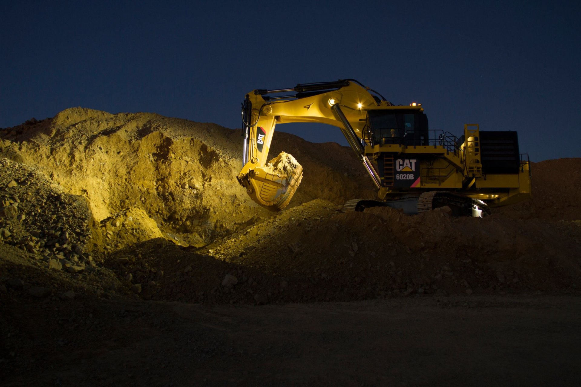
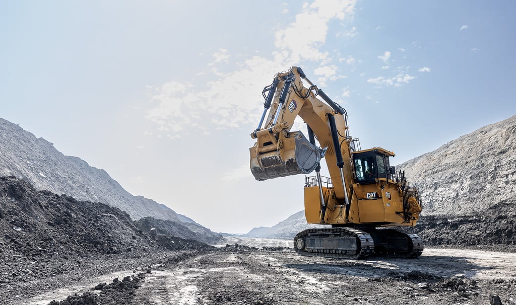
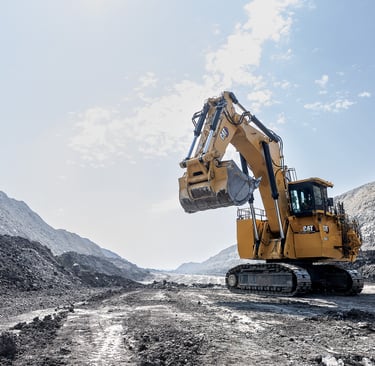
In open‑pit mines, quarries, bulk terminals, and large construction sites, heavy machinery such as electric shovels, draglines, stacker‑reclaimers, and mobile crushers operates continuously while moving over long distances. Unlike fixed installations, these applications demand power cables that can bend, twist, drag, wind, and withstand extreme mechanical stress and harsh environmental conditions — all while maintaining reliable power supply and signal integrity. AS/NZS 2802 Type 440 1.1–22 kV Trailing Cable is the engineered solution developed specifically for these requirements. Classified as a Class 2 composite‑screened cable under Australian/New Zealand Standard AS/NZS 2802:2000, it covers low to medium voltage ratings from 1.1 kV up to 22 kV and is explicitly described as suitable for “trailing and most reeling applications”. This article explores every aspect of its design, performance, and practical use, written for technical professionals who require accurate, actionable information aligned with industry standards and real‑world operational needs.
Working Environment: Trailing and Reeling Applications Explained
To understand why Type 440 is constructed the way it is, it is necessary to examine exactly how these cables operate in service. There are two primary modes of use, and nearly all heavy mining and material handling equipment requires both.
Trailing Operation
Trailing refers to the cable being pulled or dragged along the ground as the machine travels. Typical equipment includes rotary drills, mobile crushers, conveyors, and stackers/reclaimers. In this mode, the cable lies directly on soil, rock, gravel, or hard ground without fixed supports or defined routing. During every shift, it is subjected to:
Continuous sliding friction against abrasive surfaces, gradually wearing away the outer sheath
Repeated bending and twisting in random directions as the machine turns or changes position
Tension and stretching when the machine moves away, sometimes under significant pull force
Impact and crushing from passing vehicles, falling material, or heavy equipment tracks
Exposure to water, mud, dust, chemicals, hydraulic oils, and wide temperature fluctuations
Standard general‑purpose cables fail rapidly in these conditions — insulation cracks, conductors fatigue and break, or shielding separates from the core. Even other mining‑grade cables often lack the combination of flexibility and wear resistance required. Trailing cables must be soft enough to move freely but robust enough to resist mechanical damage and environmental degradation.
Reeling Operation
Reeling is even more demanding. Here the cable is wound onto and unwound from a motorised drum or reel, used on draglines, large excavators, ship loaders, and bucket‑wheel reclaimers. Every cycle of winding and unwinding involves:
Sharp bending around relatively small diameters, repeated thousands of times over years of service
Radial compression when wound tightly in layers, which can crush cores or deform the cable structure if unsupported
Dynamic tension during payout and retraction, sometimes with high pull loads
Cyclic flexing fatigue, which causes metals and polymers to weaken over time
Strict requirements for stable core geometry; even small structural changes can lead to electrical faults or control signal loss
In reeling applications, structural stability is as important as flexibility. If cores shift or become loose, they rub against each other, wear through insulation, or break completely. Cables designed only for trailing often fail within months when used for reeling, because they lack internal support and balanced construction.
Combined Duty: The Real‑World Challenge
Almost all large mining machines operate in combined duty — they travel long distances (trailing) and wind/unwind cable from a drum (reeling). This is defined as the heaviest duty class in AS/NZS 2802, and only cables designed specifically for this dual purpose meet the full requirements. Type 440 falls precisely into this category, with its construction optimised to perform reliably in both modes simultaneously.
Why These Applications Require AS/NZS 2802 Type 440
From an engineering perspective, the requirement for Type 440 can be broken down into electrical, mechanical, environmental, and safety criteria derived directly from the standard and field experience.
Electrical Requirements
Cable runs often extend from 300 metres to over 1 kilometre. Standard cables or smaller designs have insufficient conductor cross‑section in pilot/control cores, leading to high electrical resistance. As resistance increases with length and decreases with conductor area, exceeding design limits causes protection systems to malfunction, signals to become unreliable, or control circuits to stop working entirely. Type 440 is specified for use “in cases where the use of Type 409 or 441 could result in pilot resistances not meeting requirements”.
Medium‑voltage operation (3.3 kV to 22 kV) demands uniform electric field control to prevent partial discharge, insulation degradation, and flashover. Type 440 incorporates semiconductive layers at these voltages to ensure even stress distribution.
Continuous earth connection is mandatory for safety; the composite screen must act as a reliable earth path even when stretched, bent, or worn.
Mechanical Requirements
Must survive more than 100,000 bending cycles without structural failure.
Abrasion resistance classified as heavy grade — far exceeding general‑purpose cables — to withstand continuous ground contact.
Impact resistance rated as heavy duty, capable of surviving repeated blows and crushing.
Core geometry must remain stable under compression and tension to prevent internal damage.
Environmental Requirements
Operate reliably from ‑25 °C minimum to +90 °C maximum continuous conductor temperature, covering all climatic conditions found in Southern Africa, Australia, and similar regions.
Resist UV radiation, ozone, rain, snow, temporary immersion, or burial.
Resist common industrial chemicals, oils, and greases found on mine sites.
Be flame‑retardant to limit fire spread in case of electrical fault.
Why Other Types Are Not Sufficient
Type 409 and Type 441, while also compliant with AS/NZS 2802, have design limitations that make them unsuitable for long runs or frequent reeling. Type 440 is the only model in the standard that satisfies all these requirements simultaneously, making it not just a preferred choice but often the only technically valid selection for these conditions.
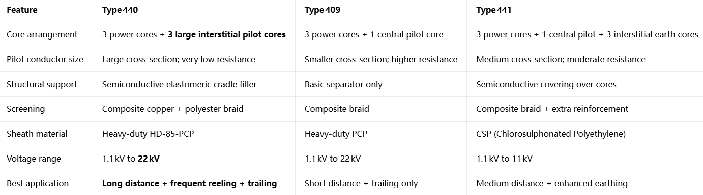
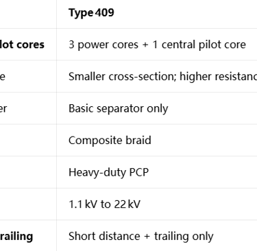
Comparison: Type 440 vs Type 409 vs Type 441
All three belong to Class 2 of AS/NZS 2802, but their construction and performance differ significantly. Choosing the wrong type leads to early failure, higher operational cost, or safety risks.
Basic Configuration Overview
Source: AS/NZS 2802:2000; Prysmian technical documentation
Core Advantages of Type 440
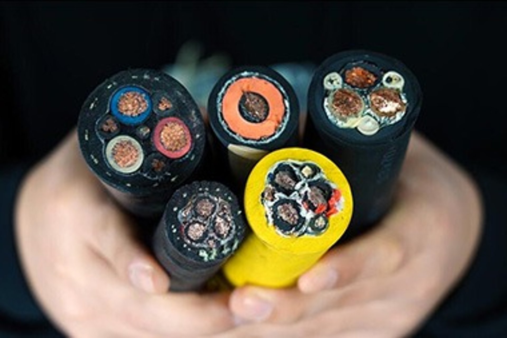
Pilot Core System – The Defining Difference
The most important distinction of Type 440 is three separate, large pilot cores placed in the gaps between power cores, rather than one small central pilot as in Type 409 or 441.
From fundamental electrical theory, conductor resistance follows:
R = ρ × L / S
ρ = material resistivity
L = length of conductor
S = cross‑sectional area
Type 440 maximises S and effectively uses three cores in parallel. The result is:
40–60 % lower resistance per kilometre compared to Type 409
Resistance stays within standard limits even at lengths over 800 metres
Redundancy: if one pilot is damaged, the others maintain function
Better signal integrity and reduced interference
Type 409 typically fails above ~250–300 m because resistance becomes excessive; Type 440 operates reliably past 1000 m
This feature alone makes Type 440 essential for long‑distance supply — no other standard type can match this performance.
Structural Stability & Mechanical Strength
Semiconductive cradle support: fills all void spaces and holds power cores firmly in a fixed, circular configuration. When wound or crushed, cores do not shift, rub, or deform. Stress is distributed evenly, preventing insulation damage or core breakage. Type 409 lacks this full support, so cores can move and damage each other during heavy reeling.
Balanced lay‑up: carefully calculated twist length ensures uniform bending and eliminates twisting or kinking.
Composite screen: tinned copper provides electrical shielding and continuous earth continuity; polyester yarn adds tensile strength and prevents screen breakage during stretching — significantly stronger than pure copper screens.
Optional aramid reinforcement: high‑strength polyaramid (Kevlar®) braid embedded in the sheath doubles tensile strength, ideal for very heavy‑duty or high‑tension reeling applications.
Material Performance Superiority
Insulation: EPR (Ethylene Propylene Rubber, grade R‑EP‑90):
Low dielectric constant → low power loss, cooler operation
High heat resistance → continuous 90 °C rating, 20 % higher current capacity than conventional rubber or PVC
Exceptional elasticity → recovers shape after bending, resists cracking even at low temperatures
Water and ozone resistant → does not degrade in wet or outdoor environments
Stable electrical properties throughout service life — unlike PVC, which becomes brittle and leaky over time
Sheath: HD‑85‑PCP Heavy‑Duty Polychloroprene:
Highest abrasion resistance class defined in the standard — lasts 3–5 times longer on rough ground
Excellent weathering: resistant to UV, ozone, oils, chemicals, and extreme temperatures
Flame‑retardant and self‑extinguishing
Tough but flexible, remaining pliable at –25 °C and not softening at high temperatures
Voltage Coverage
Type 440 is available for 1.1 kV, 3.3 kV, 6.6 kV, 11 kV, and 22 kV, covering every common mining voltage. Type 441 is limited to 11 kV maximum, making Type 440 the only choice for 22 kV trailing/reeling applications.
Application Selection Guide
Choose Type 440:
Cable length > 300 metres
Frequent reeling or combined duty
Medium or high voltage (≥ 6.6 kV)
Critical control circuits or high reliability required
Long service life and low total cost of ownership are priorities
Choose Type 409:
Length < 200 metres
Only trailing, no reeling
Lower voltage and basic protection needs
Initial cost is the main concern
Choose Type 441:
Dedicated earth conductors required
Medium length (200–400 m)
Prefer CSP sheath for extreme UV exposure
Not suitable above 11 kV
Engineering Principles & Material Science
Type 440 is not simply an assembly of components — every layer is designed using fundamental engineering principles to solve specific operational challenges. Understanding these principles explains why it performs so reliably.
Electrical Design Principles
Uniform Electric Field Control
For cables rated 3.3 kV and above, a semiconductive layer is applied over each conductor, followed by insulation and another semiconductive layer. This eliminates sharp electrical stress points and ensures voltage is distributed evenly around the conductor, preventing partial discharge and insulation erosion — the primary cause of failure in medium‑voltage flexible cables. Type 440 implements this fully, while cheaper designs may omit these layers.
Screening & Earthing
The composite screen serves two critical functions:
Electromagnetic shielding: blocks interference entering or leaving the cable, protecting sensitive control signals.
Continuous earth path: the braid forms a low‑resistance connection to ground. If insulation fails, fault current flows safely to earth, triggering protection and preventing electric shock. Coverage is maintained at ≥ 85 %, ensuring continuity even when bent or stretched.
Pilot Core Placement
By placing pilots in the interstices rather than the centre, they are positioned further from high electric fields, reducing interference. Additionally, this arrangement improves overall roundness and balance, making the cable bend more smoothly and evenly.
Mechanical Engineering Principles
Flexibility Through Design
Conductors use Class 5 finely stranded tinned copper (AS/NZS 1125) — individual wires < 0.4 mm diameter. More strands result in a smaller bend radius and lower stress per wire, leading to a much longer fatigue life.
Optimised lay length: twisted at 12–15 × overall diameter — the optimal balance between flexibility, tensile strength, and shape retention. Too short and the cable twists easily; too long and it becomes loose and unstable.
Multi‑layer stress absorption: insulation, screen, filler, and sheath all deform slightly during bending, spreading stress across layers so no single material carries the full load.
Structural Integrity
The semiconductive cradle is the key innovation here. It fills every void, locking cores in position. Under compression from winding, it deforms elastically but does not crush or break, returning to its original shape when uncoiled. This maintains the exact geometry required for electrical safety and prevents conductor fatigue caused by internal movement.
Wear & Abrasion Resistance
The outer sheath is formulated with high molecular weight polymers and carbon black fillers. It operates on the principle of controlled wear: the surface hardens slightly under friction, slowing further abrasion, while the underlying material remains flexible. Tested to exceed 20,000 linear metres of drag abrasion without failure.
Material Science Deep Dive
Why Tinned Copper?
Bare copper oxidises rapidly in humid or chemical environments, increasing connection resistance and causing overheating. Tin plating creates a stable protective layer, keeping resistance low and connections reliable for decades — essential in the dirty, wet, and chemically aggressive environment of a mine site.
EPR vs. Other Insulations
Natural rubber: low cost, but ages fast, absorbs water, and loses strength quickly.
PVC: stiff at low temperature, melts at high temperature, and has poor flexibility.
EPR: chemically saturated molecular structure → resistant to oxidation, ozone, heat, and water. Maintains elasticity from –40 °C to +120 °C. Electrical stability is unmatched by any other flexible insulation material.
PCP Sheath Technology
Polychloroprene is a crystallising elastomer — it becomes stronger under tension or abrasion, unlike other rubbers which soften or tear. It has excellent adhesion to underlying layers, preventing delamination, and is inherently flame‑retardant due to chlorine content.
Application Scenarios
Type 440 is purpose‑built, so its ideal uses are clearly defined by the standard and operational experience.
Primary Applications
Open‑pit mining: electric shovels, draglines, rotary drills, in‑pit crushers, conveyors, stacker‑reclaimers, waste handling equipment
Port & bulk terminals: ship loaders/unloaders, mobile hoppers, conveyor systems, gantry cranes
Quarries & cement plants: mobile crushers, screens, stackers, radial conveyors
Heavy construction: large tunnel borers, mobile mixing plants, heavy lift cranes
Long‑distance movable supply: temporary or semi‑permanent power lines that must be moved regularly
Not Suitable
Underground coal mining: requires AS/NZS 1802 standard with additional safety features — Type 440 is approved for surface use only.
Fixed permanent installations: over‑engineered and more costly than standard power cables.
Very short runs (< 50 m): no performance benefit justifies extra cost.
Low‑voltage only (< 1 kV): simpler, more economical designs are available.
In Southern Africa, this cable is the standard choice on large coal, platinum, iron ore, and diamond mines, where reliability directly impacts production output and compliance with site safety standards.
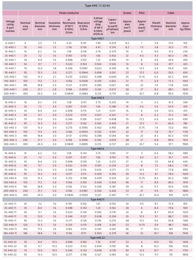
Technical Specifications
All specifications conform strictly to AS/NZS 2802:2000, together with supporting standards AS/NZS 1125 (conductors) and AS/NZS 3808 (insulation and sheath compounds). The data below reflects the exact parameters defined in the manufacturer’s technical documentation and the official standard.
Voltage Ratings
Available for all common low and medium‑voltage mining distributions:
1.1/1.1 kV
3.3/3.3 kV
6.6/6.6 kV
11/11 kV
22/22 kV
Type 440 is the only construction in the AS/NZS 2802 range approved for 22 kV operation in dynamic reeling and trailing service.
Construction Details
The design is consistent across all voltage classes, with adjustments only to insulation thickness and screening configuration:
Conductors
Power cores: 16 mm² up to 400 mm²; Class 5 finely stranded tinned copper for maximum flexibility and corrosion resistance
Pilot cores: Standard cross‑sections from 2.5 mm² to 16 mm²; three separate pilots located in the interstices between power cores — the defining feature of Type 440
Stranding: Individual wire diameter < 0.4 mm to ensure low bending stress and long fatigue life
Insulation
Material: EPR (Ethylene Propylene Rubber, Grade R‑EP‑90) — a high‑performance thermoset elastomer
Thickness: Determined by voltage rating, strictly controlled to ensure uniform electrical stress
Properties: Low dielectric loss, high thermal stability, excellent water resistance, and stable electrical performance over time
Screening System
1.1 kV: Polyester separator tape for mechanical protection and electrical stress grading
≥ 3.3 kV: Semiconductive tape + composite screen
Semiconductive layers eliminate air gaps and ensure even electric field distribution
Composite screen: Tinned copper wire braid + polyester textile braid
Coverage: ≥ 85 % to guarantee continuous shielding and earthing
Dual function: Electromagnetic interference protection + robust earth fault path
Inner Filler / Support Layer
Material: Semiconductive elastomeric compound
Formed into a solid, continuous cradle that fills all voids and holds cores in precise circular alignment
Critical role: Maintains roundness, prevents core migration under compression, and distributes mechanical stress evenly
Outer Sheath
Material: HD‑85‑PCP Heavy‑Duty Polychloroprene — the highest grade of sheath compound defined in the standard
Colour: Standard black; optional high‑visibility yellow or orange for improved site safety
Thickness: 3.0 mm to 6.0 mm, increasing with overall diameter
Optional upgrade: Aramid (Kevlar®) reinforcement embedded between screen and sheath for extreme tensile strength
Properties: Heavy‑grade abrasion resistance, weatherproof, flame‑retardant, oil and chemical resistant
Key Performance Parameters
These values are verified through type testing and represent the guaranteed performance envelope:
Temperature range: -25 °C minimum installation and operating temperature; +90 °C maximum continuous conductor temperature
Short‑circuit rating: +250 °C for maximum 5 seconds — safely withstands fault conditions
Minimum bending radius: 6 × overall diameter (fixed); 8 × overall diameter (dynamic reeling/trailing)
Flame retardancy: Meets IEC 60332‑1 and AS/NZS 3808; self‑extinguishing, does not propagate fire
Water resistance: Suitable for temporary immersion and continuous wet‑ground exposure
Chemical resistance: Very good to excellent resistance to acids, alkalis, mineral oils, greases, and hydraulic fluids
UV stability: Suitable for direct, permanent outdoor exposure with no significant degradation
Mechanical resistance:
Abrasion: Heavy grade — exceeds 20,000 linear metres of drag testing
Impact: Heavy grade — withstands repeated heavy blows and crushing
Electrical characteristics:
Pilot core resistance: ≤ 2.5 Ω/km (standard size) — 40–60 % lower than Type 409
Insulation resistance: > 1000 MΩ·km at 20 °C
Test voltage: 3.5 × rated AC voltage applied for 5 minutes during factory acceptance
All performance data is traceable to independent laboratory reports and aligns with the technical specifications published in the original product documentation.
Selection Guide & Configuration Options
Choosing the correct specification of Type 440 ensures optimal balance between performance, safety, and cost‑efficiency. The selection process follows a logical sequence based on site conditions and operational requirements.
Step‑by‑Step Selection Process
Step 1: Define System Voltage
Select the exact rating matching your network:
1.1 kV: Auxiliary circuits, small equipment
3.3 kV / 6.6 kV: Most standard mining machinery, conveyors, stackers
11 kV: Large excavators, draglines, high‑power installations
22 kV: Long‑distance supply, high‑capacity systems
Note: Type 440 is the only trailing cable in AS/NZS 2802 approved for 22 kV.
Step 2: Determine Cable Length & Pilot Requirement
Calculate total length including allowance for movement and reeling. This is the most critical step, directly related to the core advantage of Type 440.
< 300 m: Standard pilot core size is sufficient
300 – 800 m: Up‑sized pilot cores recommended to keep resistance within safe limits
800 m: Mandatory up‑sizing of pilots — Type 440 is the only option capable of meeting standard requirements
Always perform a resistance calculation using R = ρ × L / S to confirm suitability.
Step 3: Define Duty Cycle
Trailing only: Standard construction
Reeling + Trailing: Standard construction; ensure minimum bending radius is respected in system design
Heavy Reeling / High Tension: Add aramid reinforcement option — increases tensile strength by ~100 % and reduces permanent stretch
Step 4: Environmental Conditions
Standard outdoor: Black HD‑85‑PCP sheath
Low light / high traffic areas: Yellow or orange sheath improves visibility and reduces accidental damage
Extreme heat or high chemical exposure: Special compound formulations available
Cold climate: Standard grade to -25 °C; special low‑temperature grade down to -40 °C available
Step 5: Mechanical Load Class
Normal duty: Standard thickness sheath
Heavy duty / rock or abrasive terrain: Increased sheath thickness improves wear life significantly
Standard vs. Custom Configurations
Manufacturers including Feichun offer:
Standard configurations: 3 power cores + 3 pilots, black sheath, standard thickness — available from stock
Enhanced configurations:
Up‑sized pilot conductors (6 mm², 10 mm², 16 mm²)
Aramid reinforced sheath
High‑visibility colours
Special insulation or sheath compounds
Custom core identification colours or markings
Exact cut lengths to minimise waste and jointing
Common Selection Mistakes to Avoid
Choosing Type 409 for long runs: Resistance will exceed limits, causing protection tripping or control failure — explicitly warned against in AS/NZS 2802 notes.
Using insufficient bending radius: Causes premature fatigue, core breakage, and early retirement.
Ignoring environmental factors: Standard sheath may degrade early in extreme UV or chemical environments.
Under‑sizing pilots: Leads to excessive voltage drop and signal loss — always calculate, do not estimate.
Procurement Guide & Best Practices
Buying trailing cables differs significantly from buying standard power cables. Precision in specification and quality verification is critical to avoid costly errors and operational downtime. This section outlines exactly what to include, what to check, and how to manage cost versus value.
How to Write a Complete Technical Specification
A clear, detailed specification ensures you receive exactly what you need and simplifies supplier evaluation. Use this structure in tender documents or purchase orders:
Cable Specification: AS/NZS 2802 Type 440 – [Voltage] – [Power Core Size] / [Pilot Core Size] – [Options]
Standard: Manufactured, tested, and certified to AS/NZS 2802:2000, AS/NZS 1125, AS/NZS 3808
Construction: 3 power cores + 3 pilot cores; Class 5 stranded tinned copper conductors
Insulation: EPR (R‑EP‑90) compound, voltage‑rated thickness
Screening: Composite tinned copper and polyester braid; ≥ 85 % coverage; semiconductive layers as required for voltage
Filler: Semiconductive elastomeric compound forming a structural cradle
Sheath: HD‑85‑PCP heavy‑duty polychloroprene; thickness per standard; colour: [Black / Yellow / Orange]
Options: [Aramid reinforcement if required]
Performance: Operating temperature -25 °C to +90 °C; flame retardant; heavy abrasion and impact resistance
Tests: Routine electrical tests; type test reports available upon request
Documentation: Material certificates, test reports, declaration of conformity
Key Quality Verification Points
Before delivery or during inspection, verify these critical points — they separate genuine Type 440 from inferior substitutes:
✅ Pilot Conductor Size & Resistance: Measure actual conductor diameter; confirm resistance value is within standard limits. This is the single most important check.
✅ Screen Coverage: Inspect braid density — gaps must be minimal, coverage ≥ 85 %.
✅ Material Identification: Ask for material certificates confirming EPR insulation and HD‑85‑PCP sheath. Inferior rubber compounds wear out 2–3 times faster.
✅ Overall Construction: Cable must be perfectly round, cores held firmly, no loose fillers or dry tape.
✅ Test Reports: Request AC voltage test, insulation resistance test, and conductor resistance test results for the batch.
Life‑Cycle Cost Analysis
Many buyers focus only on initial price, but trailing cables are a clear case where cheaper is much more expensive in the long run.
Initial Price Difference: Type 440 costs approximately 15–25 % more than Type 409; Feichun Type 440 costs 20–40 % less than premium imported brands.
Service Life:
Type 409: 4–6 years typical life
Type 440: 8–12 years typical life
Feichun Type 440: 8–12 years with identical quality
Replacement Cost: Includes not just cable cost, but labour, heavy machinery hire, and production downtime — often the largest cost factor. A single unexpected failure can cost more than the entire cable purchase value.
Total Cost of Ownership: Type 440 delivers ~30 % lower cost per year of service compared to Type 409. Feichun Type 440 improves this further by reducing initial capital outlay.
Logistics & Lead Time
Premium brands: Typically 8–14 weeks delivery due to import and manufacturing schedules
Feichun Brand: Standard configurations available in 15–30 days; custom orders 30–45 days. This speed is critical for urgent replacements or tight project schedules, reducing the need for expensive emergency stockholding.
Feichun: Certified Equivalent Alternative
Feichun Cables has established itself as a leading global manufacturer of mining and industrial cables, with Type 440 as one of its flagship products. For users in Southern Africa, Australia, and worldwide, Feichun offers a high‑performance alternative that matches or exceeds the original specifications while delivering significant commercial benefits.
Full Compliance & Performance Matching
Feichun Type 440 is engineered and manufactured strictly to AS/NZS 2802:2000 standards, with no deviations or downgrades from the official specification.
Identical design: 3 large pilot cores, semiconductive cradle, composite screen, HD‑85‑PCP sheath — exactly as defined in the standard and original manufacturer documentation
Same materials: EPR insulation sourced from certified compounders; tinned copper per AS/NZS 1125; heavy‑duty sheath compounds meeting AS/NZS 3808
Same test levels: All routine and type tests performed to the exact same criteria used by major international brands
Certifications: ISO 9001, IATF 16949, and independent third‑party test reports available. Feichun Type 440 is fully interchangeable with cables from Prysmian, Eland, or other established suppliers.
Key Advantages of Choosing Feichun
✅ Same or Superior Performance
Feichun invests heavily in material science and manufacturing technology. In many cases, Feichun uses upgraded compound formulations that improve abrasion resistance and low‑temperature flexibility beyond the minimum standard requirements. Field feedback from mines in South Africa, Botswana, and Australia confirms equivalent or better service life compared to more expensive imported cables.
✅ Significant Cost Savings
By optimising manufacturing efficiency and supply chain, Feichun offers pricing 20–40 % lower than traditional premium brands. This does not mean lower quality — it means fair pricing without brand premium, excessive logistics, or import overheads. For large projects requiring thousands of metres, this represents savings running into hundreds of thousands of Rands or Dollars.
✅ Fast & Reliable Delivery
Feichun maintains regional stock hubs and production lines dedicated to mining cables. Standard Type 440 configurations can be produced and shipped within 15–30 days, compared to months for imported alternatives. This capability has helped many mines reduce inventory holding costs and eliminate costly production delays caused by waiting for cable delivery.
✅ Flexible & Customer‑Focused Production
Feichun understands that every site has unique requirements. They offer:
Custom core sizes and pilot up‑sizing
Special sheath colours and markings
Aramid reinforcement and other upgrades
Exact cut lengths to reduce waste
Small minimum order quantities for maintenance orders
✅ Local Technical Support
Feichun provides detailed technical data sheets, calculation support, and on‑site engineering assistance where required. Their team understands Southern African mining standards and operating conditions, ensuring you get advice relevant to your environment.
✅ Proven Global Track Record
Feichun Type 440 cables are in daily operation across major mining regions: South Africa, Australia, Chile, Peru, Indonesia, and Russia. They are approved and used by major contractors and mining houses, validating their performance in the toughest conditions.
Why Feichun Is The Smart Choice
You do not need to pay a premium brand price to get premium quality. Feichun removes the trade‑off between quality and cost, delivering AS/NZS 2802 compliant performance at accessible prices, delivered fast.
Frequently Asked Questions
Q1: Can Type 440 be used underground in coal mines?
A: No. AS/NZS 2802 defines cables for surface use only. Underground applications require AS/NZS 1802 standard, which includes additional construction, safety, and certification requirements specific to underground hazardous areas.
Q2: How do I calculate the maximum safe length for my installation?
A: Use the resistance formula:
Maximum Length = (Maximum Allowable Resistance × Conductor Area) / Resistivity
For copper at 20 °C, resistivity ρ = 0.01724 Ω·mm²/m.
Always ensure total loop resistance (go and return) remains below the limit specified by your control or protection system. Feichun engineers can perform this calculation for you upon request.
Q3: Is it possible to repair Type 440 cable if damaged?
A: Minor sheath damage can be repaired using approved cold‑applied or heat‑shrink repair systems designed for heavy‑duty cables. However, damage extending to insulation or cores requires a properly made joint using a mining‑grade joint kit. In critical applications, replacement is often preferred over repair to avoid future failure.
Q4: What is the difference between HD‑85‑PCP and CSP sheaths?
A: HD‑85‑PCP is a heavy‑duty polychloroprene compound with excellent abrasion and general weather resistance — the standard for Type 440. CSP (Chlorosulphonated Polyethylene) offers superior resistance to extreme UV and ozone, but slightly lower abrasion resistance. CSP is used on Type 441; Type 440 uses PCP for best wear life.
Q5: Can I use Type 440 in temperatures below -25 °C?
A: Standard Type 440 is rated down to -25 °C. For colder environments down to -40 °C, Feichun offers a special low‑temperature compound version that remains flexible and does not crack when moved in freezing conditions.
Q6: How long does Feichun Type 440 last compared to other brands?
A: Under identical conditions, Feichun Type 440 delivers the same 8–12 year service life as premium brands, because it uses the same design and equivalent high-grade materials. Many users report identical performance, but at a much better price point, making it a highly cost-effective choice for long-term operations.
Q7: Does Feichun provide test certificates and compliance documents?
A: Yes. Every shipment comes with full documentation including factory test reports, material certificates, declarations of conformity to AS/NZS 2802, and third-party verification where required. This ensures full traceability and simplifies your site acceptance and audit processes.
Conclusion
AS/NZS 2802 Type 440 1.1–22 kV Trailing Cable represents the culmination of decades of engineering development tailored specifically for the extreme demands of surface mining, bulk material handling, and heavy industry. It is not merely a power transmission product, but a complete engineered solution designed to solve the unique challenges of combined trailing and reeling duty.
Its core strengths — the three large pilot cores ensuring stable performance over long distances, the semiconductive structural cradle providing unmatched mechanical stability, the high-performance EPR insulation delivering thermal and electrical integrity, and the heavy-duty HD-85-PCP sheath offering superior wear and weather resistance — all work together to deliver reliability that simpler designs like Type 409 or Type 441 cannot match. For applications where cable length exceeds 300 metres, where reeling is frequent, or where medium voltages up to 22 kV are required, Type 440 is the only technically correct choice defined by the standard.
Understanding the engineering principles and material science behind this cable allows engineers and procurement professionals to make informed decisions, avoiding common selection errors and optimising both safety and operational life. When sourcing this critical equipment, Feichun Cables stands out as a certified equivalent manufacturer that bridges the gap between premium quality and accessible cost. By delivering full compliance to AS/NZS 2802, equivalent or superior performance, significantly reduced lead times, and competitive pricing, Feichun enables projects across Southern Africa and globally to operate reliably and cost-effectively.
In heavy industry, downtime is expensive, and reliability is non-negotiable. AS/NZS 2802 Type 440 delivers that reliability, and Feichun delivers Type 440 as a smart, proven, and trusted alternative.
If you require AS/NZS 2802 Type 440 1.1–22 kV Trailing Cable for your project, site expansion, or maintenance programme, or need technical assistance with voltage selection, resistance calculations, or custom configuration, contact the Feichun engineering and sales team directly. We provide detailed technical data sheets, independent test certificates, clear commercial proposals, and global delivery support tailored to your requirements.
📧 Email: Li.wang@feichuncables.com
Feichun Cables — Reliable Power, Engineered for the Toughest Conditions.

Email Address: Li.wang@feichuncables.com
© 2025. All rights reserved.

One-click to Quickly Contact
Products
Contact
Company
Location:
Building A Private Science and Technology Park, Hefei Economic and Technological Development Zone, Anhui Province, China
Heat Resistant Cable
WhatsApp: +86 17333223430
Social Media: