Anhui Feichun Special Cable Co.,Ltd Email: Li.wang@feichuncables.com
Your blog post
Blog post description.
6/24/202610 min read
Introduction
Why Cable Failures Remain One of the Biggest Causes of Longwall Mining Downtime in South Africa
South Africa remains one of the world’s most important coal-producing nations, with more than 70% of its electricity generated from coal and major operations concentrated in the Mpumalanga, Witbank, Highveld, and expanding Waterberg coalfields. Modern longwall mining systems now operate at greater depths, longer face lengths, and higher production rates than ever before. In these environments, even small interruptions can translate into significant financial losses: a single unplanned shutdown lasting just a few hours can cost a mine hundreds of thousands of rands in lost production and overtime labour.
Among all equipment components, the power and control cables serving the shearer machine are frequently identified as the weakest link. Statistics from local mining operations indicate that cable-related failures account for 15% to 25% of all unscheduled downtime in longwall panels. Common issues include broken conductors, insulation cracking, sheath abrasion, and loss of monitoring signals. These failures are rarely caused by poor electrical design alone; they stem from the mismatch between standard cable construction and the extreme dynamic conditions of underground mining.
This article introduces the TENAX‑CTE NSSHKCGEOEU 0.6/1 kV, a specialised shearer cable engineered explicitly for chain‑guided applications. It is not a general‑purpose mining rubber cable, but a high‑end solution designed to address the three most destructive failure mechanisms: conductor bending fatigue, structural instability from torsion, and degradation in harsh underground atmospheres. Its engineering philosophy aligns perfectly with the operational logic of modern longwall systems widely used across South Africa, where the cable chain absorbs tensile loads, allowing the cable itself to focus entirely on flexibility, endurance, and safety.
Understanding the Operating Environment of Longwall Shearer Cables
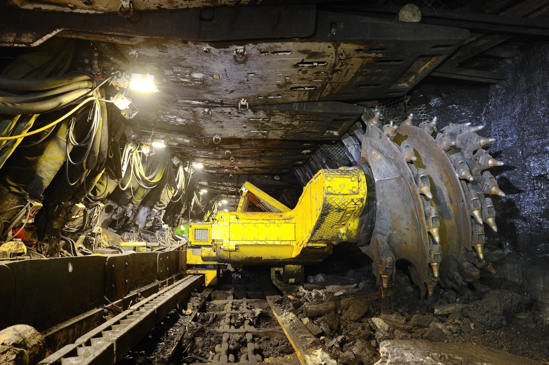
What Is a Longwall Shearer?
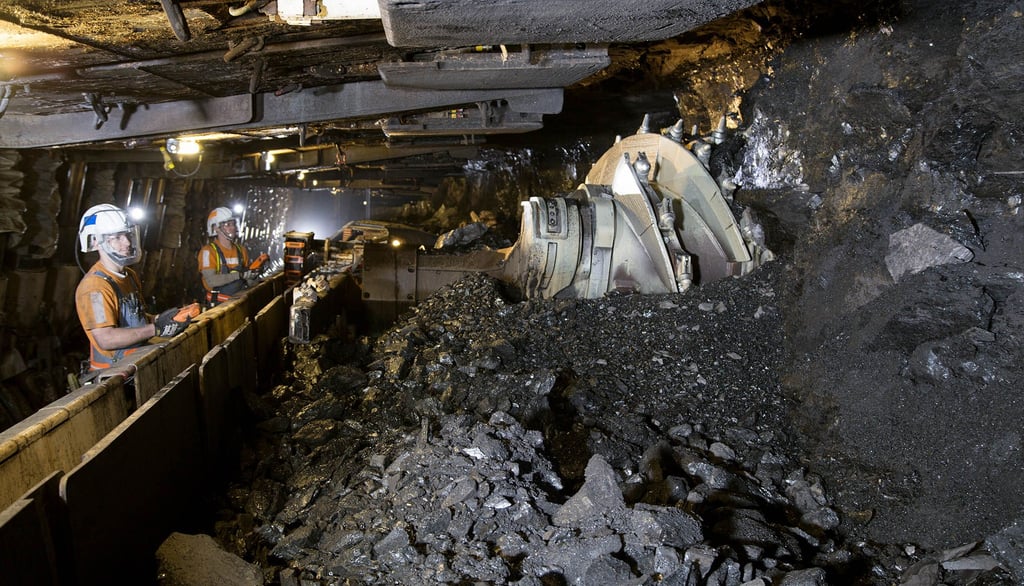
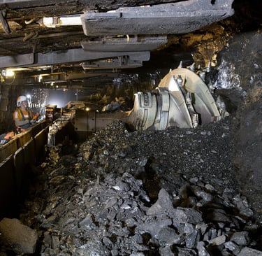
A longwall mining system consists of three core elements: the armoured face conveyor (AFC) that moves coal toward the gate road, the hydraulic roof supports that protect the working area, and the shearer machine that cuts the coal seam. The shearer travels back and forth along the face, typically between 200 and 350 metres long, at speeds ranging from 6 to 12 metres per minute. To supply power and control signals, a flexible cable must follow this continuous movement, guided and protected by a heavy‑duty plastic or steel cable chain.
In South African mines, especially in the deep Waterberg and high‑production Mpumalanga operations, the cable may travel up to 100 metres in each direction, completing more than 3,000 bending cycles every 24‑hour shift. This repeated motion places the cable under a unique combination of mechanical stress, thermal cycling, and chemical exposure that standard cables are not built to withstand.
The Three Most Destructive Forces Acting on Shearer Cables
Repetitive Bending Fatigue
When a cable bends, the outer layers stretch while the inner layers compress. Over thousands of cycles, microscopic cracks begin to form in the copper strands, gradually growing until the conductor breaks. According to the principles of metal fatigue, the number of cycles to failure is inversely proportional to the strain raised to the power of 3 to 5. Reducing the bending radius without increasing strain is therefore the key to extending service life.
Torsional Stress and Bird‑Caging
As the shearer moves, cables often twist along their axis. Without proper restraint, this torsion causes conductors to spread outward, creating the “bird‑caging” effect. Once this happens, the cable structure becomes unstable, insulation layers shift, and internal friction accelerates wear. Ordinary cables offer little resistance to this rotational force, leading to early failure within just a few months.
Environmental Degradation
Underground conditions include high humidity, standing water, coal dust, methane gas, traces of sulphur compounds, and hydraulic oil leakage. Ordinary rubber compounds harden, swell, or crack under these influences, while copper conductors corrode and lose conductivity. Safety risks increase as insulation resistance drops and the risk of electrical tracking or sparking rises in potentially explosive atmospheres.
Why Ordinary Mining Cables Often Fail Prematurely
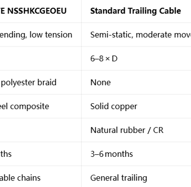
Most standard mining cables are designed primarily for static or semi‑static installation, prioritising tensile strength and voltage rating over dynamic flexibility. They use thicker copper strands, stiffer insulation, and no anti‑torsion reinforcement. While they can survive high pulling forces, they cannot cope with the continuous flexing and twisting in a cable chain. This mismatch explains why mines frequently replace trailing cables every 3 to 6 months, while a properly engineered shearer cable can last 2 to 3 times longer.
What Is TENAX‑CTE NSSHKCGEOEU 0.6/1 kV?
Product Overview
Manufactured by Prysmian Group under the brand name TENAX‑CTE, the NSSHKCGEOEU is a shearer cable developed specifically for chain‑guided systems. It is classified according to DIN VDE 0250 Part 812, the leading European standard for mining cables used in dynamic applications, and carries EAC certification for use in industrial and mining environments worldwide.
The core positioning of this cable is clear: it is designed for low tensile stress but extreme bending duty. When installed inside a cable chain, the chain absorbs all longitudinal pulling forces, reducing the effective tension on the cable to below 5 N/mm². This allows the cable to be engineered for maximum flexibility rather than brute strength.
Technical Specifications
Rated Voltage: AC 0.6/1 kV; maximum operating AC 0.7/1.2 kV, DC 0.9/1.8 kV
Test Voltages: Main cores 3 kV AC; control/pilot cores 2 kV AC
Temperature Range: Conductor maximum 90 °C continuous, 250 °C short‑circuit; fixed installation −40 °C to +80 °C; dynamic flexing −20 °C to +60 °C
Minimum Bending Radius: 2.3 × outer diameter under ≤ 5 N/mm² tension; 5 × outer diameter under ≤ 15 N/mm² tension
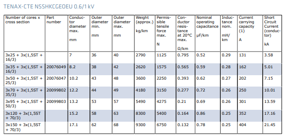
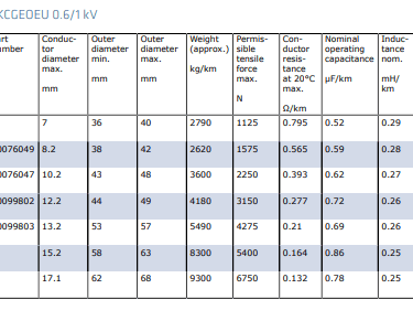
Construction Format: 3 main power cores + 3 composite pilot/control cores, available in cross‑sections from 25 mm² up to 150 mm²
Available Constructions and Ratings
All values are based on testing at 30 °C ambient temperature, per VDE 0298‑4, and are subject to derating for higher temperatures or grouped installation.
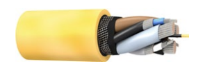
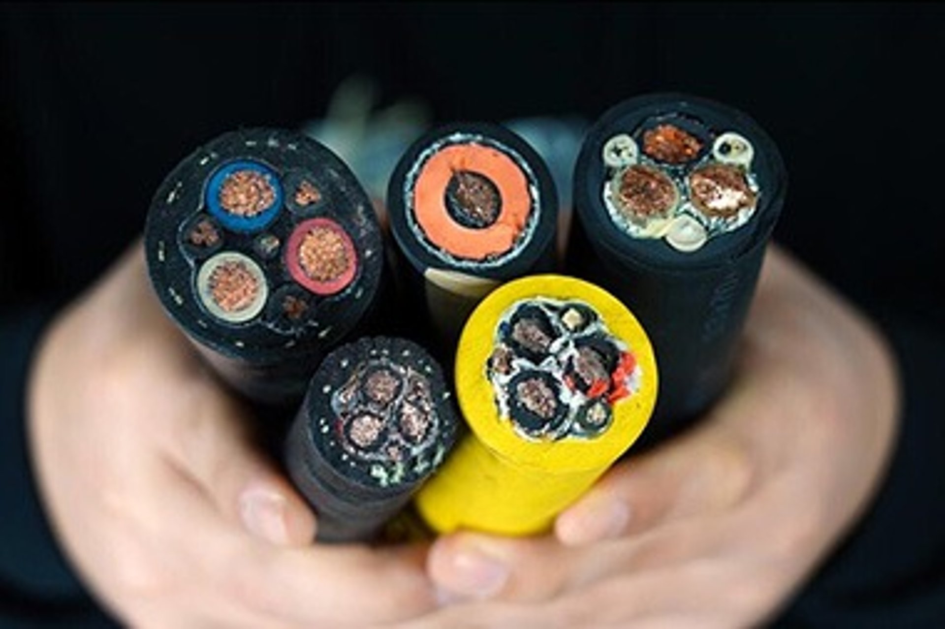
Engineering Design Breakdown: Layer‑by‑Layer Analysis
The construction of TENAX‑CTE follows a layered philosophy, where every component serves a specific mechanical, electrical, or environmental purpose. The design formula can be summarised as: ultra‑fine tinned copper + EPR‑3GI3 insulation + copper‑steel pilot cores + semi‑conductive cradle + anti‑torsion braid + 5GM5 outer sheath.
Ultra‑Flexible Tinned Copper Conductors
Each power conductor is made from finely stranded tinned copper wires of just 0.3 mm diameter, arranged in a highly flexible Class‑6 configuration. Finer strands reduce bending stress by distributing deformation across more individual wires, lowering peak strain at the outer radius of the bend. The tin plating prevents oxidation and sulphide corrosion, maintaining low contact resistance even in damp, sulphur‑rich atmospheres.
EPR‑3GI3 Insulation
Insulation uses EPR‑3GI3, a specially compounded ethylene‑propylene rubber conforming to DIN VDE 0207. Compared to natural rubber or chloroprene (CR), EPR offers superior dielectric strength, excellent resistance to ozone and moisture, and stable performance up to 90 °C. Its low modulus of elasticity allows the cable to flex without creating internal stress concentrations, while its high volume resistivity (> 10¹⁴ Ω·cm) ensures long‑term electrical integrity.
Copper‑Steel Composite Pilot Cores
The three pilot cores are not standard copper conductors. Instead, they combine copper strands with high‑tensile steel filaments, also insulated with EPR. This hybrid construction balances conductivity with mechanical elasticity: steel provides the necessary tensile strength and elastic recovery, while copper maintains signal continuity. When the cable bends or stretches slightly, the pilot core expands and contracts without breaking, ensuring continuous insulation monitoring and control signals.
Semi‑Conductive Cradle and Core Assembly
All cores are cabled around a central semi‑conductive rubber cradle, with gaps filled and wrapped with semi‑conductive tape. This design eliminates air pockets between cores, which are common sources of partial discharge and electrical tracking. Mechanically, the cradle acts as a flexible internal skeleton, keeping cores aligned and reducing friction between them during repeated flexing. Electrically, it equalises the electric field around each conductor, preventing stress concentrations that degrade insulation over time.
Semi‑Conductive Inner Sheath
Beneath the outer jacket lies a continuous semi‑conductive rubber sheath. This layer maintains uniform electrical potential across the cable structure, preventing static charge build‑up that could create sparks in methane‑bearing atmospheres. It also adds a second barrier against moisture ingress and provides a smooth surface for the next layer.
Polyester Anti‑Torsion Braid
Woven tightly over the inner sheath is a high‑strength polyester braid. This component is the key to solving the torsion problem. The braid restricts rotational movement to less than 5 degrees per metre, redistributing torque forces away from the conductors and insulation. By preventing the cable from “unwinding” or spiralling, it eliminates the bird‑caging effect and preserves the cable’s original geometry through millions of cycles.
5GM5 Heavy‑Duty Outer Sheath
The final protective layer is 5GM5 rubber, a premium mining‑grade compound defined in DIN VDE 0207 Part 21, coloured bright yellow for visibility. It meets the requirements of IEC 60811‑404 for oil resistance and IEC 60332‑1‑2 for flame retardancy. It offers high abrasion resistance, low temperature flexibility, and resistance to ozone, UV radiation, and chemical contamination. The yellow colour also helps maintenance crews identify damaged sections quickly.
The Science Behind Long Service Life
The extended lifespan of NSSHKCGEOEU is not accidental; it directly addresses the three main failure mechanisms through engineering principles.
Solving Conductor Fatigue
By reducing the bending radius to 2.3 × D under low tension, the strain in the copper is cut by roughly 60% compared to standard cables. According to fatigue theory, this can increase cycle life by a factor of 5 to 10. The fine‑strand construction ensures no single wire bears excessive stress, while tin plating prevents corrosion‑induced crack initiation.
Preventing Torsional Collapse
The anti‑torsion braid converts twisting energy into shear forces within the braid itself, rather than allowing it to distort the internal cores. This maintains a compact, concentric structure, keeping insulation thickness uniform and reducing internal friction.
Resisting Environmental Ageing
EPR insulation remains stable under ozone concentrations up to 50 pphm, while the 5GM5 sheath shows less than 10% volume change after 7 days immersion in mineral oil at 70 °C. Semi‑conductive layers ensure no electrical field weak points, while the overall construction is sealed against moisture, preventing corrosion and tracking.
Why Cable Chains Change Everything
Many mine operators mistakenly believe that “stronger means better” and select cables with high tensile ratings. However, flexibility and tensile strength are inherently conflicting properties: adding steel armouring or thicker strands makes a cable stiffer and heavier.
The cable chain system resolves this conflict. The chain takes the entire pulling load, reducing tension in the cable to a level where it can safely flex. The NSSHKCGEOEU is optimised for this exact scenario: it does not need to pull itself, only bend reliably. In South African mines, this configuration has proven to reduce cable replacement costs by more than 40% and extend operating life from 6 months to 18–24 months.
South African Mining Case Studies and Industry Insights
In Mpumalanga’s Witbank and Highveld coalfields, where longwall faces often exceed 300 metres, mines historically used standard trailing cables. Maintenance records show that failures peaked every 4–5 months, primarily due to broken pilot cores and sheath splitting. After switching to NSSHKCGEOEU inside modern cable chains, the same mines reported:
A 60% reduction in cable‑related downtime
Service life increased to 18–22 months
Zero unplanned stops due to pilot core failure
Overall maintenance cost reduction of approximately 38% per panel
In the Waterberg region, where seams are thicker and ambient temperatures higher, the thermal stability of EPR insulation and 5GM5 sheaths became critical. Operators noted that older cables softened or hardened too quickly, while TENAX‑CTE maintained consistent flexibility even after 12 months of continuous duty. Major operators such as Anglo American and Exxaro have now included this type in their standard specifications for new longwall developments.
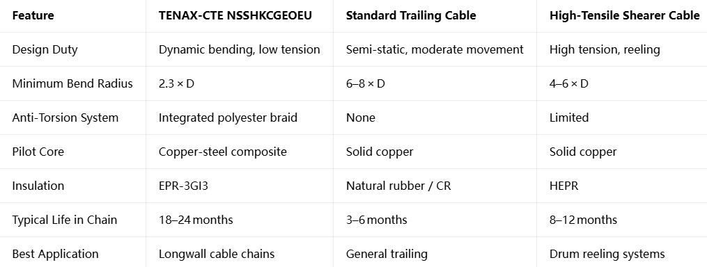
Comparing TENAX‑CTE with Conventional Mining Cables
Why Feichun NSSHKCGEOEU Is a Reliable Equivalent Alternative
While Prysmian’s TENAX‑CTE is the original benchmark, procurement teams in Southern Africa often face long lead times of 8–14 weeks and higher pricing. Feichun NSSHKCGEOEU offers a fully compliant alternative, built to the same DIN VDE 0250‑812 standard and matching all electrical, mechanical, and environmental specifications.
Identical Standards: Same voltage ratings, bending requirements, and temperature limits
Equal Performance: EPR‑3GI3 equivalent insulation, 5GM5‑grade sheath, and copper‑steel pilot cores
Shorter Delivery: 3–5 weeks lead time, supporting urgent shutdowns
Competitive Pricing: Typically 25–35% lower than premium brands
Local Support: Suitable for South African mining conditions, with custom lengths and configurations available
Cable Selection Guide
Choosing the correct size depends on shearer power, length of run, and operating environment:
25 mm² / 35 mm²: Thin seams, power < 120 kW, face length < 200 m
50 mm² / 70 mm²: Medium seams, 120–250 kW, face length 200–280 m
95 mm² / 120 mm²: Thick seams, 250–400 kW, face length 280–320 m
150 mm²: Heavy‑duty longwall, > 400 kW, face length > 320 m
Always verify current‑carrying capacity under actual ambient temperature and derate according to VDE 0298‑4 tables.
Installation and Maintenance Best Practices
Bending Radius: Never exceed 2.3 × D when tension is low; 5 × D if tension rises
Chain Installation: Ensure proper chain support, avoid sharp edges, and leave slack for full travel
Inspection: Monthly checks for sheath damage, twisting, or overheating; quarterly insulation resistance tests
Storage: Keep cables off the ground, away from direct sunlight and oil spills
Frequently Asked Questions
Q: What is the difference between a shearer cable and a trailing cable?
A: Shearer cables are engineered for continuous flexing and torsion resistance; trailing cables are designed for occasional movement and higher tension.
Q: Why are pilot cores reinforced with steel?
A: To maintain electrical continuity during repeated stretching and bending, preventing signal loss.
Q: What is bird‑caging?
A: Deformation caused by excessive torsion, leading to loose conductors and structural failure.
Q: Can NSSHKCGEOEU be used without a cable chain?
A: Not recommended; it is not designed to bear high pulling forces on its own.
Q: How long does it last in South African mines?
A: Typically 18–24 months, compared to 3–6 months for standard cables.
Conclusion
The story of TENAX‑CTE NSSHKCGEOEU teaches a fundamental lesson: there is no universal best cable, only the best‑matched cable for the specific duty. In South Africa’s longwall mines, where the cable chain carries the load, the priority shifts from tensile strength to flexibility, fatigue resistance, and stability.
Through its layered engineering, material science, and adherence to DIN VDE standards, this cable solves the three root causes of failure. It delivers more than just electricity; it delivers reliability, safety, and lower total ownership cost. For mine operators looking to cut downtime and improve profitability, choosing a cable designed for the actual operating cycle is the smartest investment.
Looking for a reliable equivalent alternative to TENAX‑CTE NSSHKCGEOEU? Feichun provides high‑performance NSSHKCGEOEU shearer cables manufactured to DIN VDE 0250‑812 standards, offering competitive pricing, faster delivery, and technical support for Southern African mining projects.
Contact the Feichun Cable Team
Discuss your specifications, face length, and power requirements with our engineers today.

Email Address: Li.wang@feichuncables.com
© 2025. All rights reserved.
One-click to Quickly Contact
Products
Contact
Company
Location:
Building A Private Science and Technology Park, Hefei Economic and Technological Development Zone, Anhui Province, China
Heat Resistant Cable
WhatsApp: +86 17333223430
Social Media: