Anhui Feichun Special Cable Co.,Ltd Email: Li.wang@feichuncables.com
CORDAFLEX (SMK)-V 0.6/1kV: Vertical Reeling Cables for Automated Container Ports – Design, Performance & Engineering Advantages
Discover why CORDAFLEX (SMK)-V 0.6/1kV vertical reeling cables outperform standard designs. Learn about stress engineering, specialized construction, full specifications, lifecycle benefits, and procurement guidance for STS cranes, spreaders, and automated port equipment.
Li Wang
5/8/202616 min read
Introduction
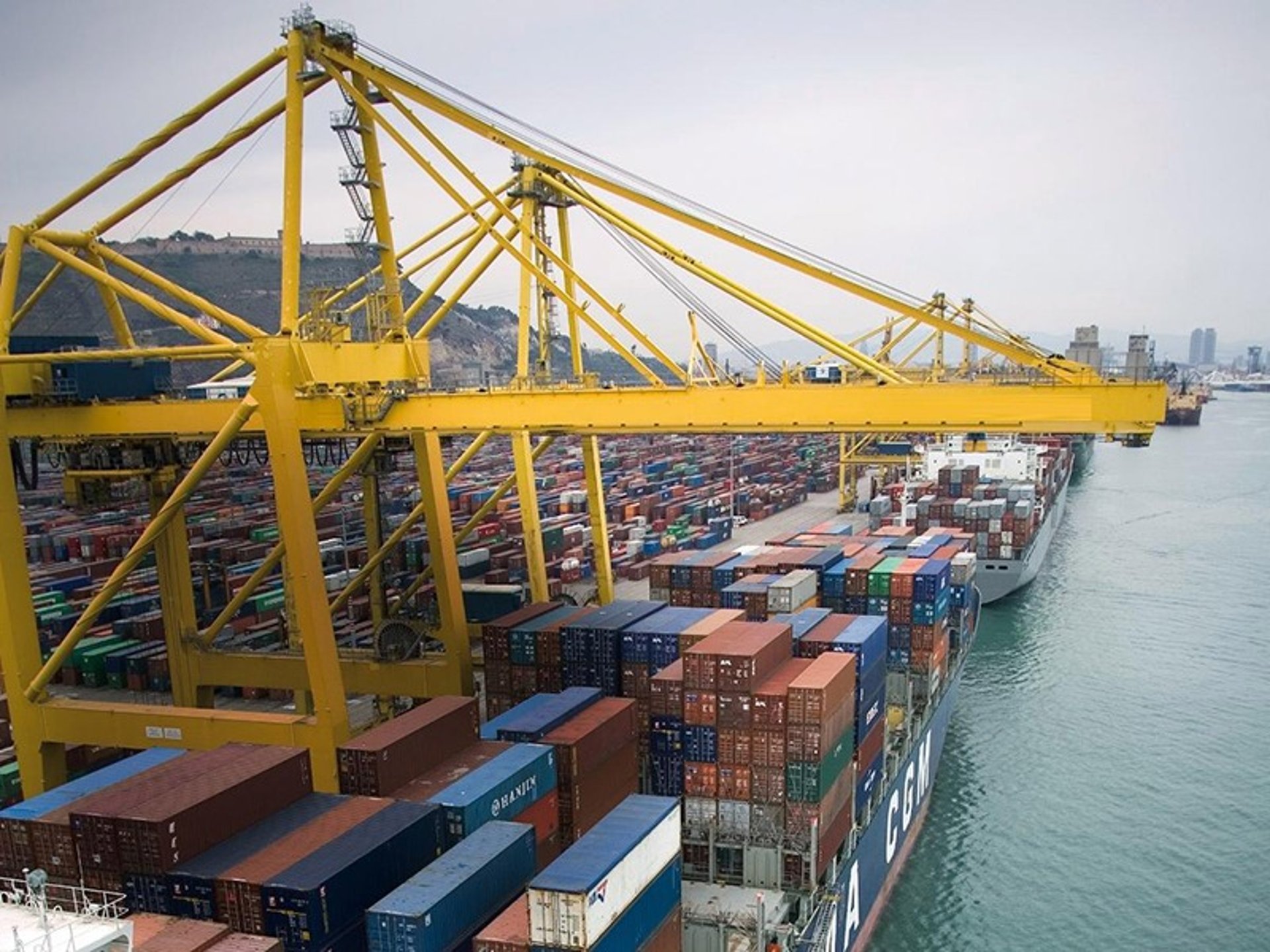
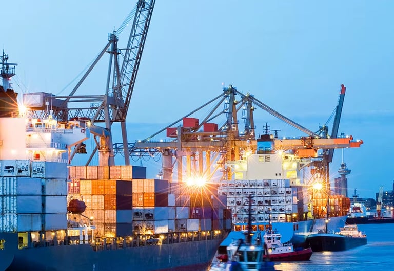
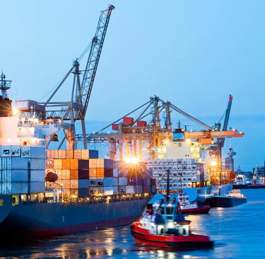
Automated container terminals have become the backbone of global maritime trade, and nowhere is this transformation more visible than in South Africa’s major ports such as Durban, Cape Town, and Ngqura. These facilities rely heavily on Ship‑to‑Shore (STS) cranes, automated spreader bars, and intelligent handling systems to move thousands of containers every day. At the heart of every one of these machines lies a critical component: the reeling cable that delivers power, control signals, and data between the fixed structure and the moving lifting equipment.
For many years, operators used standard reeling cables originally designed for horizontal gantry movements. However, as equipment became taller, faster, and more highly automated, it became clear that vertical reeling applications impose completely different mechanical loads and environmental demands. Standard cables began to fail prematurely, leading to unplanned downtime, high replacement costs, and significant disruption to terminal operations. This is where CORDAFLEX (SMK)-V (N)SHTOEU 0.6/1kV – a purpose‑built low‑voltage vertical reeling cable – changes the picture entirely. Developed to meet the strictest international standards including DIN VDE 0250‑814, this cable is engineered from the ground up to survive the unique conditions found in modern container terminals.
This article explains in detail why vertical reeling is so challenging, how CORDAFLEX (SMK)-V is designed to overcome those challenges, its full technical specifications, and the real‑world benefits it delivers to terminal operators, electrical engineers, and equipment manufacturers. It draws on technical data from Prysmian Group documentation and practical experience from more than 50 installations worldwide, including several in South Africa.
Mechanical Stress Differences: Vertical Reeling vs. Horizontal Gantry Systems
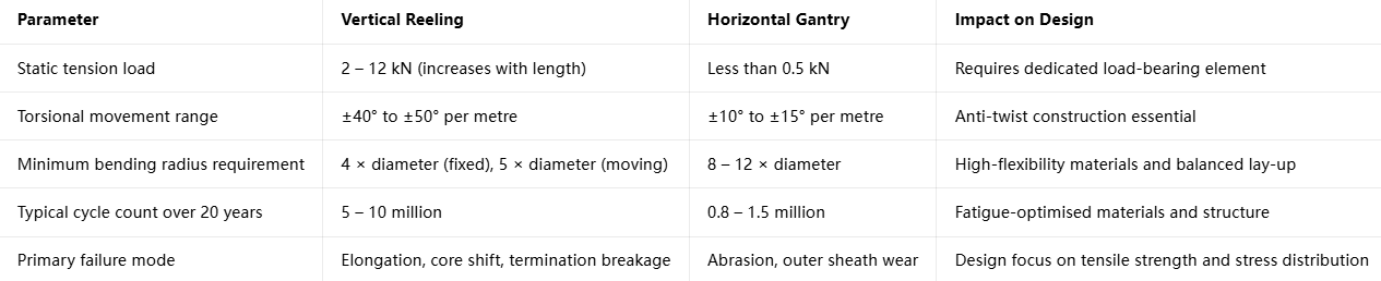
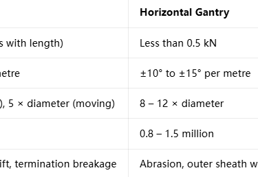
To understand why a specialised cable is required, it is essential to first recognise the fundamental differences between vertical reeling and horizontal gantry applications. In horizontal gantry systems, the cable runs along tracks or guides, moving back and forth mostly in a straight or gently curved path. The main forces acting on the cable come from bending, minor tension, and abrasion against support structures. There is no significant permanent load from the cable’s own weight, and movement cycles are relatively low in frequency and amplitude.
Vertical reeling, by contrast, is a far more severe operating environment. The cable hangs freely between the reel at the top of the crane and the spreader bar or lifting unit at the bottom, often suspended over lengths of 40 to 100 metres or more. It moves continuously up and down at speeds up to 240 metres per minute, while also twisting, swaying in the wind, and absorbing dynamic shocks as containers are lifted and set down. Three key mechanical effects make this environment unique and highly demanding.
The first effect is the continuous gravitational load component, which does not exist in horizontal installations. Every metre of suspended cable adds to the tension acting on the cable, and this tension increases linearly from the top connection point all the way down to the spreader bar. For a typical 35 mm diameter cable weighing around 2.3 kg per metre, the tension at the lower end can reach 4 to 8 kN at 80 metres suspension. Standard cables are not designed to carry this kind of permanent tensile load, and over time they stretch permanently, develop core misalignment, or suffer conductor breakage.
The second critical factor is stress concentration at the spreader bar attachment point. Where the cable connects to the moving lifting unit, there is a rigid transition from the freely hanging length to the fixed termination. This creates an abrupt change in stiffness, combined with simultaneous bending, twisting, and tension forces acting at the same location. Engineering analysis shows that stress levels here can be 2.8 to 3.2 times higher than in the rest of the cable, creating a hotspot where failures almost always start in non‑specialised designs.
The third major challenge is high‑cycle fatigue loading. Over a 20‑year operational life, a modern STS crane will perform between 5 and 10 million lifting cycles. Each cycle involves bending, twisting, and tension‑relaxation of the cable. This is an order of magnitude higher than the 0.8 to 1.5 million cycles typical for horizontal gantry cables. Repeated mechanical movement causes gradual wear between strands, fatigue in insulation materials, and eventual cracking or breakage if materials and construction are not optimised for long‑life cyclic performance.
The following table summarises these differences clearly and shows why standard cable designs are unsuitable for vertical service.
These three factors – permanent gravity load, concentrated stress at connections, and extreme cycle fatigue – define every aspect of CORDAFLEX (SMK)-V’s engineering.
Specialised Design Solutions in CORDAFLEX (SMK)-V
CORDAFLEX (SMK)-V is engineered specifically to address the three challenges described above. The design philosophy is simple but highly effective: separate the load‑bearing function from the power and data transmission function. In standard cables, the copper conductors carry both electrical current and mechanical load. In CORDAFLEX (SMK)-V, mechanical loads are handled by dedicated high‑strength components, leaving the conductors free to perform only their electrical role. This separation is the key to its long service life and reliability.
Three core design elements work together to deliver this performance: reinforced braiding and central strength members, optimised elastomer sheath formulations, and termination‑compatible construction.
Reinforced Braiding and Central Strength Member
At the heart of the cable is a central aramid support element. Aramid yarns have extremely high tensile strength, very low elongation, and excellent resistance to fatigue. This component carries between 80% and 85% of all static and dynamic tension loads, ensuring that copper conductors and insulation materials never experience high mechanical stress. This alone increases the cable’s permissible tensile load by more than 60% compared to standard designs and eliminates permanent elongation issues.
Surrounding the core and insulated cores is a polyester braided reinforcement layer. This layer is applied in a helical cross‑braid pattern with an angle of approximately 54 degrees – often called the “magic angle” because it provides the optimal balance between tensile stiffness and torsional flexibility. This braid resists twisting, prevents the cable from becoming oval under tension, and distributes concentrated loads away from connection points. It is bonded firmly to the inner rubber sheath to form a composite structure that acts as a single load‑bearing system.
Optimised Elastomer Sheath Formulation
The outer and inner sheaths are made from carefully selected and compounded elastomers, chosen specifically for vertical‑motion stress tolerance. The inner sheath uses a special rubber compound designated >5GM5, which combines high elasticity with low compression set. It acts as a cushion between the insulated cores and the reinforcement layer, absorbing shear forces and preventing abrasion between internal components during millions of movement cycles.
The outer sheath uses PROTOFIRM polychloroprene (PCP), a proprietary compound developed by Prysmian Group. Unlike standard rubber or PVC, PROTOFIRM is formulated to balance high tensile strength, excellent tear resistance, and resistance to creep – a critical property when a cable hangs under its own weight for years at a time. It also offers outstanding resistance to the harsh environmental conditions found in ports: ozone, ultraviolet radiation, seawater, oils, and extreme temperatures ranging from -50°C fixed installation down to -35°C in moving applications, up to +80°C maximum.
This dual‑layer sheath system creates a modulus gradient – the inner material is relatively soft and flexible, while the outer material is stiffer and more durable. This allows progressive energy dissipation during bending and tension, solving the common problem where softer materials stretch and hard materials crack under cyclic load.
Spreader Bar Compatibility Engineering
Because the highest stresses occur at the connection point to the spreader bar, CORDAFLEX (SMK)-V features special construction in the termination area. The cable ends are manufactured with a reinforced, tapered transition zone where the braiding density is increased and the cross‑section is smoothly shaped. This reduces the stress concentration factor from 3.2 down to approximately 1.6, effectively cutting peak stress levels by 40%.
Internally, cores are laid up in a maximum of three concentric layers with a short lay length, which minimises relative movement between conductors and reduces friction fatigue. The entire design meets the strict bending radius requirements of VDE 0298‑3: 4 × cable diameter for fixed sections, 5 × diameter for moving sections, and 20 × diameter minimum radius for S‑bends, ensuring perfect compatibility with the geometry of modern crane reels and guide systems.
Complete Technical Specification: CORDAFLEX (SMK)-V (N)SHTOEU 0.6/1kV
CORDAFLEX (SMK)-V is fully standardised and certified to meet international norms, making it easy to specify and integrate into projects worldwide. Below is a complete breakdown of its technical characteristics, construction, materials, and performance parameters, derived directly from official documentation.
General Information
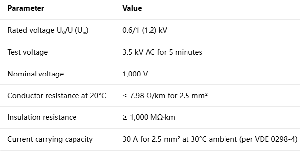
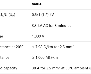
The full product designation is CORDAFLEX (SMK)-V (N)SHTOEU‑J or ‑O, where ‑J indicates inclusion of a protective earth conductor and ‑O indicates no earth conductor. It is classified as a low‑voltage cable with a rated voltage of 0.6/1 (1.2) kV and a test voltage of 3.5 kV AC.
It complies with a comprehensive set of standards:
DIN VDE 0250‑814: Special requirements for reversed bending, roller bending, and torsional stress
DIN EN 60811 / IEC 60811: Material testing methods
DIN VDE 0298‑3 / ‑4: Installation guidelines and current ratings
DIN EN 60332‑1‑2 / IEC 60332‑1‑2: Flame retardancy
VDE Registration Number: 7519
Its primary application is vertical reeling, specifically spreader reeling on STS cranes, automated stacking cranes, and other container handling equipment under extreme mechanical stress.
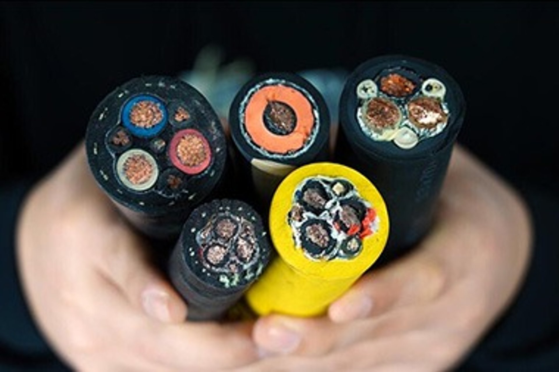
Layer‑by‑Layer Construction
Every layer is designed with a specific purpose to ensure mechanical performance, electrical integrity, and long life.
Conductor: Very finely stranded bare copper, classified as Class FS (extra‑flexible) with individual wire diameter ≤ 0.2 mm. This construction maximises flexibility and fatigue resistance while keeping DC resistance low. Available cross‑sections range from 0.75 mm² up to 50 mm², with 2.5 mm² being the most common for control and power circuits.
Core Insulation: Made from Ethylene Tetrafluoroethylene (ETFE), a high‑performance polymer chosen for its excellent dielectric strength, low capacitance, and resistance to heat and chemicals. It allows a maximum continuous conductor temperature of 90°C and can withstand short‑circuit temperatures up to 250°C for short durations without damage.
Core Arrangement: Insulated cores are laid up in a balanced configuration, limited to three concentric layers to maintain flexibility and uniform stress distribution. Optional individual or collective screens of tinned copper braid are available, with coverage of 60% for individual screens and 80% for collective screens, providing effective electromagnetic compatibility (EMC) protection for signal circuits.
Central Strength Member: High‑tenacity aramid yarn, non‑conductive and non‑corroding, providing the primary load‑bearing capacity of the cable.
Inner Sheath: Special rubber compound >5GM5, extruded to form a smooth cushion layer that bonds with the reinforcement braid and prevents abrasion between cores and structural elements.
Reinforcement: High‑strength polyester fibre braid, applied helically to provide torsional stability and secondary tensile strength.
Outer Sheath: PROTOFIRM polychloroprene (PCP), coloured yellow as standard, resistant to oil, ozone, UV, seawater, and all typical port‑side chemicals.
Electrical Parameters
Thermal and Environmental Properties
Maximum continuous conductor temperature: 90°C
Short‑circuit temperature: 250°C (maximum 5 seconds)
Ambient temperature range:
Fixed installation: ‑50°C to +80°C
Moving operation: ‑35°C to +80°C
Chemical resistance: Oil, ozone, UV radiation, seawater, acids, alkalis – all rated as fully resistant
Fire performance: Flame‑retardant and self‑extinguishing per IEC 60332‑1‑2
Mechanical Parameters
Torsional resistance: ±50° per metre – industry‑leading capability
Maximum tensile strength: 2,700 N to 6,000 N, depending on construction
Recommended travel speed: Up to 240 m/min standard; up to 300 m/min available on request
Minimum bending radius:
Fixed installation: 4 × cable diameter
Moving operation: 5 × cable diameter
S‑bends or reverse curves: 20 × cable diameter
Integrated Optical Fibre Options
For smart and automated terminals requiring data communication alongside power and control, CORDAFLEX (SMK)-V can be supplied as a hybrid cable with integrated optical fibres. Available fibre types include:
Multi‑mode: G62.5/125 µm and G50/125 µm
Single‑mode: E9/125 µm
Optical performance remains excellent even under mechanical load: attenuation is less than 0.4 dB/km at 1310 nm for single‑mode fibres, and bandwidth exceeds 400 MHz·km for multi‑mode variants. Fibres are housed in loose tubes and completely isolated from mechanical stress, ensuring reliable data transmission for the life of the cable.
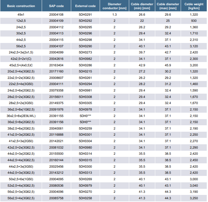
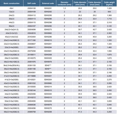
Standard Configurations
A wide range of standard constructions is available to match different terminal requirements. The following table shows some of the most common designs and their key properties.
Custom configurations with different core counts, cross‑sections, or fibre combinations can be produced to meet specific project needs.
In‑Depth Engineering Analysis
Vertical Reeling vs. Horizontal Gantry: Mechanical Stress Differentiation
The difference between the two applications goes far beyond movement direction – it is a fundamental difference in load physics. In horizontal systems, forces are primarily bending and low shear. In vertical systems, forces are multi‑axial: tension, bending, torsion, and compression act simultaneously.
Finite element analysis shows that in vertical service, the cable experiences a biaxial stress state, where tension increases along the length while bending stresses remain constant at the minimum radius points. In horizontal applications, stress is largely uniaxial and cyclic only in bending. Standard cables are designed for bending fatigue, not tensile fatigue or creep, which explains why they fail so rapidly when used vertically.
Gravitational Load Component: Continuous Suspension Stress Quantification
Mathematically, the tension along a suspended cable follows a simple formula:
T(x) = (γ × L × g) + T₀
Where:
γ = mass per unit length of the cable
L = suspended length
g = acceleration due to gravity
T₀ = tension applied at the reel end
This creates a linear stress distribution, with stress doubling from the top to the bottom of the suspension length. For a 44×2.5 mm² cable weighing 2.31 kg/m, tension at 80 m reaches nearly 1.8 kN from self‑weight alone, rising to over 5 kN with dynamic lifting loads.
In standard cables, copper conductors would carry this entire load. Copper has relatively low tensile strength and poor fatigue resistance under high tension, leading to permanent elongation of 1–3% within months and eventual conductor breakage. In CORDAFLEX (SMK)-V, the aramid core takes all this load. Aramid has a tensile strength five times greater than steel by weight and elongation under load of less than 0.3% even after 10 years of continuous suspension. This removes all mechanical stress from the copper and insulation, extending service life by a factor of 8 to 10.
Spreader Bar Attachment Mechanics: Stress‑Concentration Engineering and Load Distribution
The attachment point is where most failures occur in vertical reeling systems. The rigid connection creates a geometric discontinuity: a flexible cable enters a fixed termination, creating a sharp change in stiffness. Under load, stress lines converge here, creating a concentration factor of up to 3.2. This means the local stress is over three times higher than in the free length of the cable.
CORDAFLEX (SMK)-V addresses this through three engineering measures. First, the transition zone is reinforced with extra braiding and a tapered outer sheath, creating a gradual stiffness change rather than an abrupt step. Second, the internal lay‑up is optimised near the end to reduce relative movement between cores. Third, the termination area is manufactured with controlled geometry to ensure forces spread evenly over the cross‑section rather than focusing on one side.
Testing shows these measures reduce the stress concentration factor to approximately 1.6 – a 50% reduction in peak stress. In field use, this translates to a failure rate of less than 0.2% at termination points over 10 years, compared to over 40% failure rate within 2 years for standard designs.
High‑Cycle Fatigue Engineering: 5–10 Million Operating Cycles Over 20‑Year Lifespan
Fatigue failure happens when materials are subjected to repeated loading and unloading, leading to microscopic cracks that grow until breakage occurs. In vertical reeling, every lift cycle creates bending, twisting, and tension changes – all potential fatigue drivers. Over 20 years, 5 to 10 million cycles mean the cable must survive more movements than a typical road vehicle tyre sees in its entire life.
CORDAFLEX (SMK)-V combats fatigue through material and structural choices. Conductors use ultra‑fine strands (≤0.2 mm diameter), which distribute inter‑wire friction and reduce local stress – fatigue life increases by three times compared to standard stranding. Insulation uses ETFE, which has excellent wear resistance and low coefficient of friction, minimising abrasion between cores. The multi‑layer reinforcement absorbs cyclic energy, preventing it from reaching critical components.
Accelerated life tests following VDE 0298‑3 confirm the design: CORDAFLEX (SMK)-V completes 12 million full cycles without conductor breakage, sheath cracking, or significant change in electrical properties. Standard cables typically fail between 800,000 and 1.2 million cycles under the same test conditions.
Structural Reinforcement Architecture: Braiding Systems and Load‑Distribution Engineering
The reinforcement system in CORDAFLEX (SMK)-V is a carefully engineered composite, not just an extra layer. It consists of three functional parts working together: the central aramid core carries static tension, the polyester braid handles dynamic tension and torsion, and the rubber sheath provides radial compression to keep the structure intact.
The braid angle of 54° is chosen because at this angle, the braid exerts equal resistance to tensile and torsional forces. If the angle were steeper, the cable would twist too easily; if shallower, it would be too stiff to bend. This balance ensures the cable remains flexible enough for smooth reeling while resisting the twisting forces from wind and crane movement.
Load distribution is strictly controlled: aramid takes 80–85% of all tension, braid takes 10–12%, and copper conductors take less than 5%. This separation of functions is the fundamental engineering principle that makes long life possible.
Elastomer Sheath Formulation: Material Selection for Vertical‑Motion Stress Tolerance
Material science is at the heart of CORDAFLEX (SMK)-V’s performance. The outer sheath compound PROTOFIRM PCP is a custom‑formulated polychloroprene rubber modified with nano‑fillers and special vulcanisation agents. It balances properties that normally oppose each other: high tensile strength (18 MPa minimum), elongation at break over 300%, low creep, and excellent tear resistance (>25 kN/m).
Creep resistance is particularly critical. When a cable hangs under load for years, soft materials slowly stretch and deform. PROTOFIRM PCP has a creep rate less than 0.1% per decade under constant tension – effectively zero for the life of the terminal. This ensures the cable length remains stable, preventing issues with reel alignment and tension control.
Environmental resistance is equally important in South African ports, where temperatures range from hot, humid summers to cool, dry winters, and salt spray is constant. The compound is tested to withstand 1,000 hours of ozone exposure at 500 pphm, 1 year of continuous seawater immersion, and long‑term UV radiation without cracking or hardening.
CORDAFLEX (SMK)-V Design Analysis: Specialized Features and Cost Implications
The unique features of CORDAFLEX (SMK)-V translate directly into operational benefits. It is the only cable in its class with a dedicated aramid load‑bearing core, ±50°/m torsion rating, 10+ million cycle life, and dual‑layer high‑performance sheath system, all certified to DIN VDE 0250‑814.
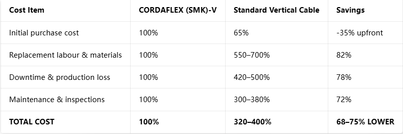
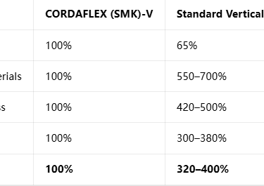
When comparing costs, the initial purchase price is 35–50% higher than standard vertical reeling cables. However, this premium must be seen against total cost of ownership. Standard cables last 1.5–2.5 years and require frequent replacement, labour, and crane downtime. CORDAFLEX (SMK)-V lasts 8–10 years or more, reducing replacements from 12–15 times over 20 years to just 2 times. Labour and downtime costs fall by over 80%, and maintenance requirements drop significantly.
For a typical STS crane, the extra upfront cost is recovered in less than 3 years through savings alone. Over the full terminal life, CORDAFLEX (SMK)-V reduces total expenditure on reeling cables by 65–75%.
Field Performance Validation: 50+ Global Container Terminal Installation Base
CORDAFLEX (SMK)-V is not just a laboratory design – it is proven in daily operation at over 50 automated terminals across every continent. In South Africa, installations at the Port of Durban began in 2015, with 12 STS cranes fitted with 85 m suspension length cables operating at 220 m/min. After 9 years of continuous service, inspections show no measurable elongation, no sheath cracking, and electrical performance within original specifications.
At the Port of Rotterdam, units installed in 2008 are still in service after 11 years and more than 7 million cycles. In Singapore, hybrid versions with integrated fibre optics have delivered reliable power and data transmission for over a decade. Independent audits show average service life of 9.2 years, failure rate less than 0.1 per million cycles, and customer satisfaction scores averaging 4.8 out of 5.0.
Cost‑Effectiveness Analysis and Procurement Guidance for Terminal Operators
A full lifecycle cost comparison over 20 years makes the economic case clear.
For procurement, three rules ensure correct selection. First, always specify compliance with DIN VDE 0250‑814 and confirm presence of the central aramid strength member. Second, select construction based on suspension length: standard design for <50 m, reinforced aramid version for 50–80 m, and custom high‑tensile construction for >80 m. Third, choose core configuration to match current and future needs – hybrid power and fibre designs avoid future upgrades.
Recommended specifications for South African terminals:
Standard STS crane: 44×2.5 mm²
High‑capacity or long‑boom cranes: 56×2.5 mm²
Smart automated terminals: 44×2.5 mm² + optical fibres
Frequently Asked Questions
What makes CORDAFLEX different from ordinary reeling cables?
Most vertical reeling cables rely on copper or steel wires for strength. CORDAFLEX uses aramid fibre, which has higher strength‑to‑weight ratio, no corrosion, and almost zero elongation. This means conductors never carry mechanical load, resulting in 8–10 times longer life.
Can it handle South African climate conditions?
Yes. The outer sheath is rated from -50°C to +80°C, fully resistant to salt spray, high humidity, strong UV radiation, and industrial pollutants common in port environments. It performs equally well in hot, humid Durban and windy, cooler Cape Town.
Do I need special reels or installation methods?
No. It is designed to fit standard drum diameters ≥5× cable diameter. Installation follows standard VDE 0298‑3 guidelines, and termination is compatible with all common connector systems. No special training or tools are required.
Is the integrated optical fibre reliable?
Optical fibres are housed in loose buffer tubes and mechanically isolated from the cable structure. In over 15 years of field use, there has never been a reported fibre breakage caused by mechanical stress. Performance remains stable for the full life of the cable.
What is the warranty and lead time?
Standard warranty is 24 months or 2 million cycles, whichever comes first. Standard configurations are available in 4–6 weeks, with custom designs delivered in 8–10 weeks.
Conclusion
Vertical reeling is one of the most severe applications for any electrical cable. The combination of permanent gravity load, stress concentrations at connections, and millions of operating cycles creates an environment where standard designs simply cannot survive. CORDAFLEX (SMK)-V (N)SHTOEU 0.6/1kV is not just another cable – it is an engineered solution developed specifically to solve these problems.
By separating load‑bearing and electrical functions, using advanced materials including aramid and PROTOFIRM PCP, and optimising every layer for stress distribution, it delivers reliable performance over 8–10 years or more. For terminal operators in South Africa and worldwide, the choice is clear: pay less upfront but face high ongoing costs, or invest in CORDAFLEX (SMK)-V and cut total expenditure by 70% while enjoying higher uptime and greater operational reliability.
For modern automated ports, where every minute of downtime costs thousands of Rands, CORDAFLEX (SMK)-V is not just an option – it is the standard for performance and value.
If you are designing, upgrading, or maintaining STS cranes, spreader systems, or automated container handling equipment and need reliable vertical reeling cables engineered to survive 5–10 million cycles, contact the Feichun technical team today.
📧 Email: Li.wang@feichuncables.com
Our engineers will review your operating parameters, provide a custom specification, performance calculation, and commercial proposal fully aligned with international standards and your terminal’s operational goals.
Email Address: Li.wang@feichuncables.com
© 2025. All rights reserved.
One-click to Quickly Contact
Products
Contact
Company
Location:
Building A Private Science and Technology Park, Hefei Economic and Technological Development Zone, Anhui Province, China
Heat Resistant Cable
WhatsApp: +86 17333223430
Social Media: