Feichun (N)TSCGEWOEU TENAX TTS-LWL: Medium Voltage Reeling Cable with Fibre-optics
Feichun TENAX TTS-LWL (N)TSCGEWOEU Medium Voltage Reeling Cable with Integrated Fiber Optics: Designed for High-stress Industrial Applications
Category | Parameter | Details |
|---|---|---|
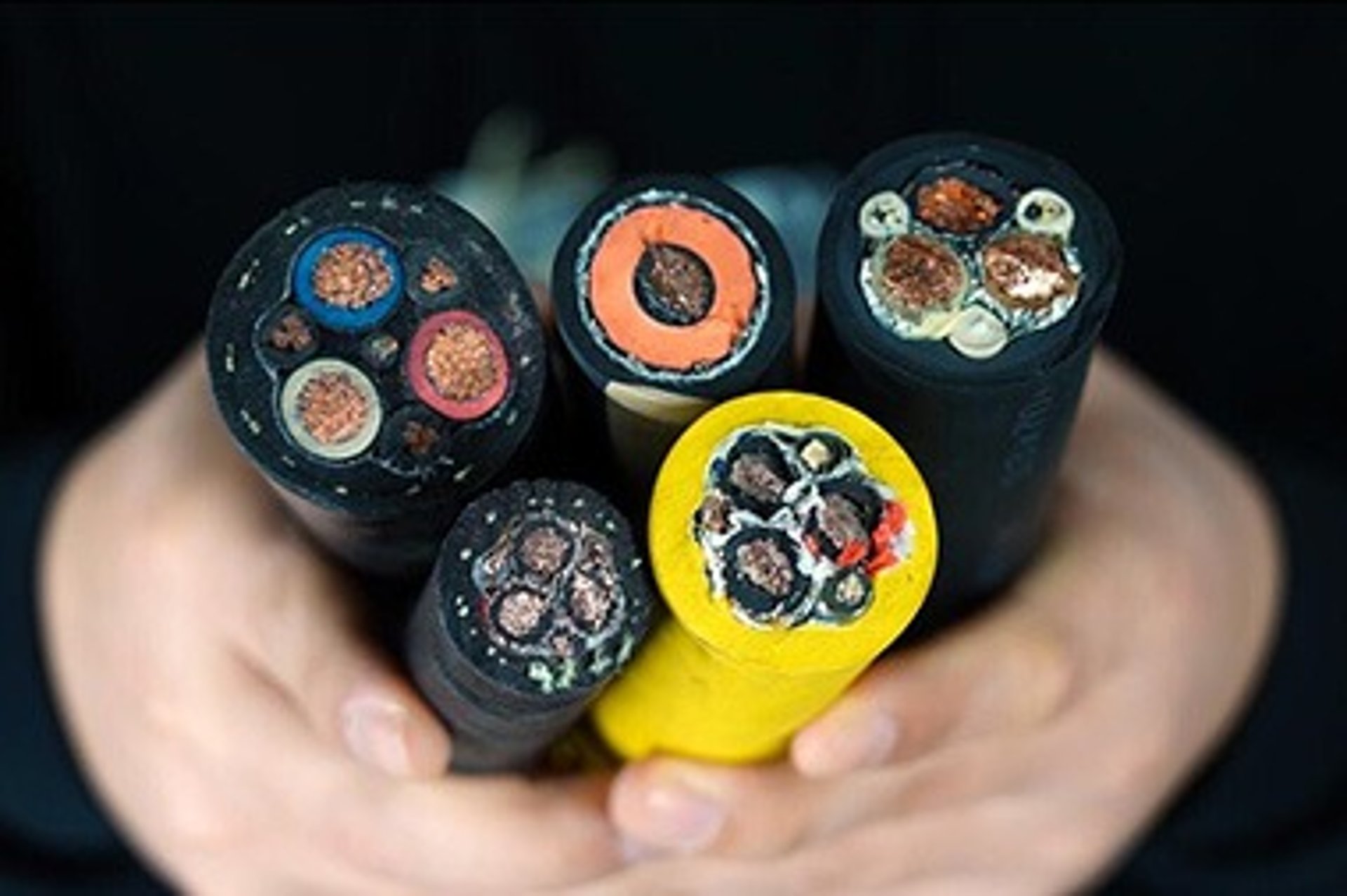
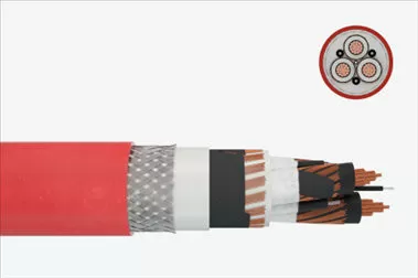
Application | Description | Flexible medium voltage reeling cable with integrated fibre-optics for combined energy and data transmission under high mechanical stresses (e.g., high travel speeds, dynamic tensile loads, multiple directional changes, roller churning, torsional stresses). Mainly for mobile equipment like fast-moving container cranes and large moving equipment. |
Global Data | Brand | Feichun TENAX-TTS |
Type Designation | (N)TSCGEWOEU | |
Standard | Based on DIN VDE 0250-813 | |
Design Features | Conductor | Plain copper, fine stranded class 5 per DIN EN 60228 / VDE 0295 |
Insulation | Rubber, compound type EPR-SHS EI6, super-clean | |
Electrical Field Control | Inner and outer layer of semiconductive rubber compound | |
Optical Fiber | 12 fibers: 50/125µ, 62.5/125µ, or E9/125µ, within protection jacket | |
Fibre Class | G50/125μm, G62.5/125μm, E9/125μm | |
Fibre Type | Graded-index fibre, Graded-index fibre, Monomode fibre | |
Attenuation at 850 nm | <2.8 dB/km (G50), <3.3 dB/km (G62.5), - (E9) | |
Attenuation at 1300 nm | <0.8 dB/km (G50), <0.9 dB/km (G62.5), <0.4 dB/km (E9) | |
Attenuation at 1550 nm | - (G50), - (G62.5), <0.3 dB/km (E9) | |
Bandwidth at 850 nm | >400 MHz (G50), >200 MHz (G62.5), - (E9) | |
Bandwidth at 1300 nm | >1200 MHz (G50), >500 MHz (G62.5), - (E9) | |
Numerical Aperture | 0.2 ± 0.02 (G50), 0.27 ± 0.02 (G62.5), - (E9) | |
Chromatic Dispersion at 1300 nm | - (G50), - (G62.5), <3.5 ps/nm km (E9) | |
Chromatic Dispersion at 1550 nm | - (G50), - (G62.5), <18 ps/nm km (E9) | |
Core Arrangement | Cores laid up around conductive filler with aramid rope in the center | |
Inner Sheath | Rubber, special compound, mechanical properties acc. to 5GM3 | |
Reinforcement | Polyester anti-torsion braid | |
Outer Sheath | Abrasion and tear-proof special rubber compound, quality at least 5GM5 per DIN VDE 0207 part 21, resistant to ozone, UV, and oil | |
Sheath Colour | Red or black with yellow stripe | |
Marking | Embossed: (N)TSCGEWOEU (number of cores) x (cross-section) (rated voltage) DRAKA DE VDE (Year of manufacture) TENAX TTS | |
Electrical Parameters | Rated Voltage | 3.6/6 kV, 6/10 kV, 8.7/15 kV, 12/20 kV, 18/36 kV |
Max. Permissible Operating Voltage AC | 4.2/7.2 kV, 6.9/12 kV, 10.4/18 kV, 13.9/24 kV, 18/36 kV | |
Max. Permissible Operating Voltage DC | 5.4/10.8 kV, 9/18 kV, 13.5/27 kV, 18/36 kV | |
AC Test Voltage | 11 kV, 17 kV, 24 kV, 29 kV | |
Current Carrying Capacity Description | According to DIN VDE 0298 Part 4 | |
Thermal Parameters | Max. Permissible Temperature at Conductor | 90 °C |
Max. Short Circuit Temperature of the Conductor | 250 °C | |
Ambient Temperature for Fixed Installation | Min -40 °C; Max +80 °C | |
Ambient Temperature in Fully Flexible Operation | Min -25 °C; Max +80 °C | |
Mechanical Parameters | Max. Tensile Load on the Conductor | 20 N/mm² |
Max. Tensile Load on the Conductor During Acceleration | 25 N/mm² | |
Torsional Stress | ± 50 °/m | |
Min. Bending Radius | According to DIN VDE 0298 part 3 | |
Min. Distance with S-type Directional Changes | 20 x D | |
Travel Speed - Reeling Operation | Up to 180 m/min |
What Makes the TENAX TTS-LWL (N)TSCGEWOEU Unique?
The TENAX TTS-LWL (N)TSCGEWOEU stands out as a hybrid solution that seamlessly integrates medium voltage power conductors with fiber optic cables, enabling simultaneous transmission of energy and high-speed data. This dual functionality reduces the need for separate power and data cables, simplifying installation and maintenance while enhancing operational efficiency.
Key Features at a Glance
Hybrid Design: Combines pure copper conductors for power with 12 fiber optic fibers for data transmission.
High Mechanical Stress Resistance: Built to withstand dynamic tensile loads, torsional stress, and high travel speeds up to 180 m/min.
Wide Voltage Range: Supports multiple voltage ratings, including 3.6/6 kV, 6/10 kV, 8.7/15 kV, and 12/20 kV.
Environmental Resilience: Resistant to UV radiation, ozone, oil, and abrasion, ensuring durability in harsh industrial settings.
Thermal Stability: Operates at conductor temperatures up to 90°C and tolerates short-circuit temperatures up to 250°C.
Compliance: Meets international standards like DIN VDE 0250-813 and GOST-R, ensuring global applicability.
Applications in Industrial Settings
The TENAX TTS-LWL (N)TSCGEWOEU is designed for environments where high mechanical stress and simultaneous power and data transmission are critical. Its primary applications include:
Container Crane Systems: Used in high-speed cranes at ports and terminals, ensuring reliable power and data flow for real-time control and monitoring.
Industrial Automation: Supports robotic systems and automated assembly lines requiring seamless power and data integration.
Mining Operations: Provides durability and flexibility for large mobile equipment in harsh mining environments.
Marine and Offshore Applications: Ideal for cranes, winches, and other equipment in offshore industries, where resistance to environmental factors is essential.
High-Speed Material Handling: Powers conveyor systems and automated sorting lines with real-time data capabilities.
Comparative Advantages Over Traditional Cables
The TENAX TTS-LWL (N)TSCGEWOEU offers several advantages over conventional power and data cables:
Integrated Design: Eliminates the need for separate cables, reducing installation complexity and costs.
Versatile Fiber Options: Supports multiple fiber types, catering to diverse data transmission needs.
Superior Mechanical Flexibility: Handles dynamic loads and high travel speeds without compromising performance.
Environmental Durability: Resists UV, ozone, oil, and abrasion, ensuring long-term reliability.
Global Compliance: Meets stringent standards like DIN VDE 0250-813 and GOST-R, making it suitable for international markets.
Installation Considerations
Installing the TENAX TTS-LWL (N)TSCGEWOEU requires careful attention to its unique design:
Fiber Optic Handling: Use specialized techniques to avoid damaging the delicate fiber optic components.
Tensile Load Limits: Adhere to the maximum tensile load of 20 N/mm² (25 N/mm² during acceleration) to prevent conductor damage.
Bending Radius: Follow DIN VDE 0298 part 3 guidelines to ensure optimal performance during directional changes.
Environmental Factors: Ensure proper routing to protect the cable from excessive exposure to mechanical stress or environmental hazards.
Frequently Asked Questions (FAQs)
What industries benefit most from the TENAX TTS-LWL (N)TSCGEWOEU?The cable is ideal for port logistics, mining, industrial automation, marine applications, and high-speed material handling systems, where high mechanical stress and simultaneous power/data transmission are required.
How does the hybrid design improve efficiency?By integrating power and fiber optic data transmission, the cable reduces the need for multiple cables, simplifying installation and maintenance while enabling real-time data for automation and monitoring.
Is the cable suitable for South Africa’s climate?Yes, its UV, ozone, and oil-resistant sheath ensures durability in South Africa’s diverse climates, from coastal humidity to arid mining regions.
What voltage ratings are available?The cable supports 3.6/6 kV, 6/10 kV, 8.7/15 kV, and 12/20 kV, catering to various industrial power requirements.
How does the cable handle high mechanical stress?Its fine-stranded copper conductors, anti-torsion braid, and robust rubber sheaths allow it to withstand tensile loads up to 25 N/mm² and torsional stress of ±50°/m.
The TENAX TTS-LWL (N)TSCGEWOEU is a groundbreaking hybrid cable that redefines industrial power and data transmission. Its ability to combine high-voltage conductors with advanced fiber optic technology makes it a versatile solution for demanding applications like container cranes, mining equipment, and automated systems. In South Africa, where port efficiency and mining safety are critical, this cable addresses current challenges by enhancing performance, reducing maintenance, and ensuring durability in harsh environments.
Rated Voltage 3.6/6 kV
Number of cores x cross section | Conductor diameter max. (mm) | Outer diameter min. (mm) | Outer diameter max. (mm) | Bending radius free moving min. (mm) | Weight (ca.) (kg/km) | Permissible tensile force max. (N) | Dynamic tensile force max. (N) | Conductor resistance at 20°C max. (Ω/km) | Nom. operating capacitance (µF/km) | Inductive Reactance (at 50Hz) (Ω/km) | Current carrying capacity (1) (A) | Short Circuit Current (conductor) (kA) |
|---|---|---|---|---|---|---|---|---|---|---|---|---|
3x25 + 2x25/2 + 1x(12G62,5) | 6.2 | 38.5 | 41.5 | 415 | 2380 | 1500 | 1875 | 0.78 | 0.38 | 0.102 | 131 | 3.58 |
3x35 + 2x25/2 + 1x(12G62,5) | 7.7 | 41.5 | 44.5 | 445 | 2750 | 2100 | 2625 | 0.55 | 0.49 | 0.092 | 202 | 5.01 |
3x50 + 2x25/2 + 1x(12G62,5) | 9.3 | 44.5 | 47.5 | 475 | 3100 | 3000 | 3750 | 0.39 | 0.49 | 0.092 | 202 | 7.15 |
3x70 + 2x35/2 + 1x(12G62,5) | 11.5 | 50 | 54 | 540 | 4400 | 4200 | 5250 | 0.27 | 0.55 | 0.088 | 250 | 10.01 |
3x95 + 2x50/2 + 1x(12G62,5) | 12.8 | 54 | 58 | 580 | 5300 | 5700 | 7125 | 0.21 | 0.62 | 0.084 | 301 | 13.59 |
3x150 + 2x70/2 + 1x(12G62,5) | 16.5 | 63 | 67 | 670 | 7600 | 9000 | 11250 | 0.13 | 0.73 | 0.08 | 404 | 21.45 |
3x185 + 2x95/2 + 1x(12G62,5) | 18.5 | 67 | 72 | 720 | 9200 | 11100 | 13875 | 0.11 | 0.79 | 0.078 | 461 | 26.46 |
Number of cores x cross section | Part number | Conductor diameter max. (mm) | Outer diameter min. (mm) | Outer diameter max. (mm) | Bending radius free moving min. (mm) | Weight (ca.) (kg/km) | Permissible tensile force max. (N) | Dynamic tensile force max. (N) | Conductor resistance at 20°C max. (Ω/km) | Nom. operating capacitance (µF/km) | Inductive Reactance (at 50Hz) (Ω/km) | Current carrying capacity (1) (A) | Short Circuit Current (conductor) (kA) |
|---|---|---|---|---|---|---|---|---|---|---|---|---|---|
3x25 + 2x25/2 + 1x(12G62,5) | 20091982 | 6.2 | 40 | 43 | 430 | 2480 | 1500 | 1875 | 0.78 | 0.35 | 0.104 | 131 | 3.58 |
3x35 + 2x25/2 + 1x(12G62,5) | 20074719 | 7.7 | 42 | 45 | 450 | 2950 | 2100 | 2625 | 0.55 | 0.39 | 0.099 | 162 | 5.01 |
3x50 + 2x25/2 + 1x(12G62,5) | 20096115 | 9.3 | 45 | 48 | 480 | 3480 | 3000 | 3750 | 0.39 | 0.45 | 0.094 | 202 | 7.15 |
3x70 + 2x35/2 + 1x(12G62,5) | 20092017 | 11.5 | 51 | 55 | 550 | 4710 | 4200 | 5250 | 0.27 | 0.51 | 0.09 | 250 | 10.01 |
3x95 + 2x50/2 + 1x(12G62,5) | 20086347 | 12.8 | 55 | 59 | 590 | 5550 | 5700 | 7125 | 0.21 | 0.58 | 0.086 | 301 | 13.59 |
3x120 + 2x70/2 + 1x(12G62,5) | 14.9 | 58.5 | 62.5 | 625 | 6700 | 7200 | 9000 | 0.16 | 0.63 | 0.084 | 352 | 17.16 | |
3x150 + 2x70/2 + 1x(12G62,5) | 16.5 | 63 | 67 | 670 | 7600 | 9000 | 11250 | 0.13 | 0.69 | 0.082 | 404 | 21.45 | |
3x240 + 2x120/2 + 1x(12G62,5) | 21 | 73 | 78 | 780 | 12400 | 14400 | 18000 | 0.08 | 1.05 | 0.08 | 540 | 34.32 |
Number of cores x cross section | Part number | Conductor diameter max. (mm) | Outer diameter min. (mm) | Outer diameter max. (mm) | Bending radius free moving min. (mm) | Weight (ca.) (kg/km) | Permissible tensile force max. (N) | Dynamic tensile force max. (N) | Conductor resistance at 20°C max. (Ω/km) | Nom. operating capacitance (µF/km) | Inductive Reactance (at 50Hz) (Ω/km) | Current carrying capacity (1) (A) | Short Circuit Current (conductor) (kA) |
|---|---|---|---|---|---|---|---|---|---|---|---|---|---|
3x25 + 2x25/2 + 1x(12G62,5) | 6.2 | 42 | 45 | 450 | 2700 | 1500 | 1875 | 0.78 | 0.3 | 0.11 | 139 | 3.58 | |
3x35 + 2x25/2 + 1x(12G62,5) | 20091668 | 7.7 | 45 | 49 | 490 | 2960 | 2100 | 2625 | 0.55 | 0.33 | 0.105 | 172 | 5.01 |
3x50 + 2x25/2 + 1x(12G62,5) | 9.3 | 50 | 54 | 540 | 3960 | 3000 | 3750 | 0.39 | 0.37 | 0.099 | 215 | 7.15 | |
3x70 + 2x35/2 + 1x(12G62,5) | 20114426 | 11.5 | 53 | 57 | 570 | 4760 | 4200 | 5250 | 0.27 | 0.42 | 0.094 | 265 | 10.01 |
3x95 + 2x50/2 + 1x(12G62,5) | 20153431 | 12.8 | 58 | 62 | 620 | 5760 | 5700 | 7125 | 0.21 | 0.48 | 0.089 | 319 | 13.59 |
3x120 + 2x70/2 + 1x(12G62,5) | 14.9 | 64 | 68 | 680 | 7265 | 7200 | 9000 | 0.16 | 0.52 | 0.087 | 371 | 17.16 | |
3x150 + 2x70/2 + 1x(12G62,5) | 16.5 | 68 | 72 | 720 | 8500 | 9000 | 11250 | 0.13 | 0.57 | 0.085 | 428 | 21.45 | |
3x185 + 2x95/2 + 1x(12G62,5) | 18.5 | 72 | 77 | 770 | 9900 | 11100 | 13875 | 0.11 | 0.61 | 0.083 | 488 | 26.46 |
Number of cores x cross section | Part number | Conductor diameter max. (mm) | Outer diameter min. (mm) | Outer diameter max. (mm) | Bending radius free moving min. (mm) | Weight (ca.) (kg/km) | Permissible tensile force max. (N) | Dynamic tensile force max. (N) | Conductor resistance at 20°C max. (Ω/km) | Nom. operating capacitance (µF/km) | Inductive Reactance (at 50Hz) (Ω/km) | Current carrying capacity (1) (A) | Short Circuit Current (conductor) (kA) |
|---|---|---|---|---|---|---|---|---|---|---|---|---|---|
3x25 + 2x25/2 + 1x(12G62,5) | 20076107 | 6.2 | 45 | 48 | 480 | 2890 | 1500 | 1875 | 0.78 | 0.24 | 0.115 | 139 | 3.58 |
3x35 + 2x25/2 + 1x(12G62,5) | 7.7 | 47 | 50 | 500 | 3250 | 2100 | 2625 | 0.55 | 0.27 | 0.109 | 172 | 5.01 | |
3x50 + 2x25/2 + 1x(12G62,5) | 9.3 | 51 | 55 | 550 | 4050 | 3000 | 3750 | 0.39 | 0.3 | 0.103 | 215 | 7.15 | |
3x70 + 2x35/2 + 1x(12G62,5) | 11.5 | 56 | 60 | 600 | 4850 | 4200 | 5250 | 0.27 | 0.34 | 0.098 | 265 | 10.01 | |
3x95 + 2x50/2 + 1x(12G62,5) | 12.8 | 60 | 64 | 640 | 6450 | 5700 | 7125 | 0.21 | 0.38 | 0.094 | 319 | 13.59 | |
3x120 + 2x70/2 + 1x(12G62,5) | 14.9 | 66 | 70 | 700 | 7700 | 7200 | 9000 | 0.16 | 0.41 | 0.091 | 371 | 17.16 | |
3x150 + 2x70/2 + 1x(12G62,5) | 16.5 | 69 | 73 | 730 | 8550 | 9000 | 11250 | 0.13 | 0.45 | 0.089 | 428 | 21.45 | |
3x185 + 2x95/2 + 1x(12G62,5) | 18.5 | 75 | 79 | 790 | 10600 | 11100 | 13875 | 0.11 | 0.49 | 0.086 | 488 | 26.46 |