Anhui Feichun Special Cable Co.,Ltd Email: Li.wang@feichuncables.com
How to fix degraded mining cable grounding connections?
Learn professional methods to diagnose and repair degraded mining cable grounding connections. Essential guide for South African mining professionals covering SANS compliance, safety procedures, and preventative maintenance strategies.
Li.wang@Feichun Cable
7/22/202511 min read
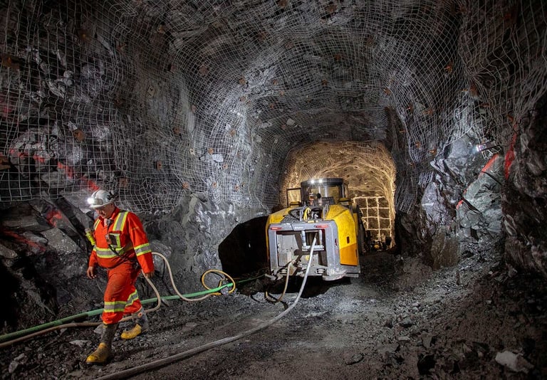
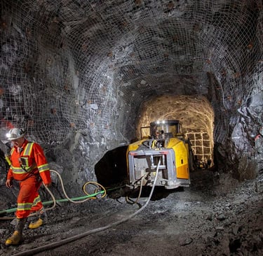
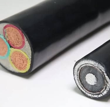
Mining cable grounding connections form the backbone of electrical safety in South Africa's extensive mining operations, from the platinum mines of the Bushveld Complex to the gold fields of the Witwatersrand. These critical safety systems protect both equipment and personnel by providing a reliable path for fault currents to earth. However, the harsh underground environment presents unique challenges that can degrade grounding connections over time, potentially leading to catastrophic failures.
In South Africa's mining sector, which contributes significantly to the country's GDP, electrical incidents remain a serious concern for mine safety officers and electrical engineers. The Mining Qualifications Authority (MQA) consistently emphasises the importance of proper grounding systems as part of comprehensive electrical safety protocols. When grounding connections deteriorate, the consequences extend beyond equipment damage to include potential loss of life and significant operational downtime.
Understanding how to properly diagnose and repair degraded grounding connections is essential for maintaining safe mining operations. This comprehensive guide addresses the specific challenges faced by South African mining operations, incorporating local regulatory requirements and real-world solutions developed in the field.
What Causes Grounding Connections to Degrade?
Environmental Factors: The Underground Challenge
South African mines operate in particularly challenging environments where moisture, dust, and corrosion work together to compromise electrical connections. The high water table in many Gauteng mining areas creates persistent moisture problems, whilst the mineral-rich groundwater accelerates corrosion processes. Salt deposits from underground water sources create conductive paths that can bypass intended grounding circuits.
Dust accumulation, particularly the fine particles generated during drilling and blasting operations, creates insulating layers that interfere with proper electrical contact. When combined with moisture, this dust forms corrosive paste that accelerates the degradation of copper and steel grounding components.
Mechanical Strain: Movement and Vibration
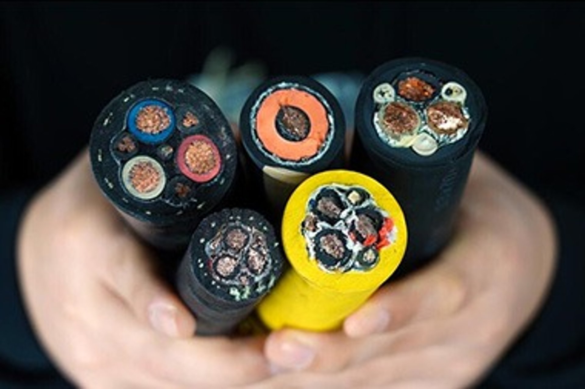
Underground mining operations subject cables to constant mechanical stress through equipment movement, blasting vibrations, and thermal expansion cycles. Mining cables must accommodate the movement of mobile equipment whilst maintaining reliable grounding connections. Improper cable tension management often leads to stress concentration at connection points, causing gradual loosening or conductor fracture.
The cyclical loading experienced during conveyor operations and the impact forces from rockfall or equipment collision create fatigue conditions that gradually weaken grounding connections. Cable reeling systems, commonly used for mobile equipment power supply, impose additional mechanical stresses that can compromise grounding integrity if not properly managed.
Chemical Exposure and Thermal Stress
Mining environments expose cables to various chemicals used in ore processing and equipment maintenance. Hydraulic fluids, cutting oils, and chemical reagents can degrade cable insulation and corrode grounding connections. The elevated temperatures encountered in deep-level mining operations, particularly in South Africa's gold mines which extend to depths exceeding 3,000 metres, create thermal cycling that expands and contracts connection hardware.
Exposure to mine gases, including hydrogen sulphide and carbon dioxide, creates corrosive conditions that attack metallic grounding components. These gases, combined with moisture, form weak acids that gradually dissolve copper and steel elements in grounding systems.
Poor Installation and Aging Infrastructure
Many South African mines operate with electrical infrastructure installed decades ago, when grounding standards were less stringent than current SANS requirements. Legacy installations often lack proper corrosion protection or use connection methods that don't meet modern reliability standards.
Poor initial installation practices, including inadequate cleaning of connection surfaces, incorrect torque application, or use of dissimilar metals, create conditions for accelerated degradation. The lack of proper training for installation personnel contributes to recurring grounding problems in many operations.
Warning Signs of Grounding Failure
Voltage Drop During Regular Testing
Regular earth continuity testing reveals increasing resistance values that indicate degrading connections. When voltage drop measurements exceed acceptable limits during routine testing, immediate investigation is required. The gradual increase in earth loop impedance provides early warning of developing problems before complete failure occurs.
Trending test results over time helps identify patterns that indicate specific failure modes. Sudden increases in measured resistance often correlate with mechanical damage, whilst gradual increases typically indicate corrosion or loosening connections.
Visual Inspection Indicators
Visible corrosion appears as green or blue discolouration around copper connections, or rust formation on steel components. Heat damage manifests as discoloured insulation or oxidised metal surfaces around connection points. Loose hardware becomes apparent through visual inspection, including backed-out nuts, displaced washers, or gaps in connection assemblies.
Physical damage to cable sheaths near grounding points often indicates mechanical stress problems that compromise both insulation and grounding integrity. White powdery deposits around connections suggest galvanic corrosion between dissimilar metals.
Equipment Behaviour Changes
Erratic equipment behaviour, including unexplained shutdowns, nuisance tripping of protection devices, or inconsistent motor performance, often indicates grounding problems. Earth leakage protection devices may begin operating at lower fault levels, indicating reduced system impedance margins.
Increased electromagnetic interference affecting communication systems or electronic equipment can result from poor grounding that allows noise currents to flow through unintended paths. Equipment displaying increased sensitivity to switching transients often indicates compromised grounding connections.
Measurable Parameters
Increased earth leakage current measurements during routine testing indicate insulation degradation that often accompanies grounding problems. Phase-to-earth voltage measurements that deviate from normal values suggest grounding system imbalances that require investigation.
Power quality measurements showing increased harmonic distortion or voltage fluctuations may indicate grounding problems that affect system neutral point stability. These parameters provide quantitative evidence of developing grounding issues before visible symptoms appear.
Standard Diagnostic Procedure
Visual Inspection Protocol
Systematic visual inspection begins with de-energising circuits and following lockout-tagout procedures required by mine safety protocols. Examine all accessible grounding connections for signs of corrosion, mechanical damage, or loose hardware. Document findings with photographs for maintenance records and trend analysis.
Check cable entry points for proper sealing and strain relief installation. Inspect cable sheath condition for cuts, abrasions, or chemical damage that might compromise grounding conductors. Verify that grounding conductor connections use proper hardware and maintain required torque specifications.
Electrical Testing Procedures
Voltage drop testing measures the resistance of grounding conductors under load conditions. Apply the test current specified in SANS 1520-1 and measure voltage across the grounding conductor length. Calculate resistance values and compare with acceptable limits for the conductor size and length.
Continuity testing verifies the integrity of grounding circuits from equipment frames to the main earthing terminal. Use appropriate test equipment to measure low resistance values accurately, ensuring test currents don't damage sensitive electronic components that might be connected to the grounding system.
Insulation Integrity Assessment
Perform insulation resistance testing between grounding conductors and other circuit conductors to verify that grounding systems don't compromise overall circuit insulation. Apply test voltages appropriate for the cable voltage rating and maintain test duration sufficient to detect polarisation effects.
High-potential testing may be required for critical circuits to verify insulation capability under overvoltage conditions. These tests must be performed according to manufacturer specifications and mine safety procedures to prevent equipment damage.
Step-by-Step Repair Methods
A. Tightening Loose Connections
Tools Required:
Calibrated torque wrench appropriate for connection hardware
Wire brush for surface cleaning
Contact cleaner spray
Anti-corrosion compound
Personal protective equipment including insulated gloves
Procedure: De-energise the circuit and verify zero energy state using appropriate lockout-tagout procedures. Remove existing connections and clean all contact surfaces using wire brushes to remove corrosion and contaminants. Apply contact cleaner to ensure optimal conductivity between mating surfaces.
Reassemble connections using proper torque specifications from the manufacturer's installation instructions. Apply torque in incremental steps to ensure even pressure distribution across the connection interface. Mark bolt positions to facilitate future inspection for loosening.
Apply anti-corrosion compound to external surfaces while avoiding contamination of the actual contact surfaces. This protective coating prevents moisture ingress and reduces galvanic corrosion between dissimilar metals.
B. Cleaning Corroded Areas
Materials and Process: Use appropriate contact cleaners that don't leave conductive residues or damage cable insulation materials. Abrasive brushes should be matched to the base metal to avoid creating galvanic cells through contamination with dissimilar metals.
Remove corrosion products completely, as partially cleaned surfaces often accelerate future corrosion through crevice formation. Apply anti-corrosion grease specifically designed for electrical connections, ensuring compatibility with cable insulation materials.
For severe corrosion, replacement of affected hardware may be more cost-effective than attempting restoration. Document the extent of corrosion damage for trend analysis and preventative maintenance planning.
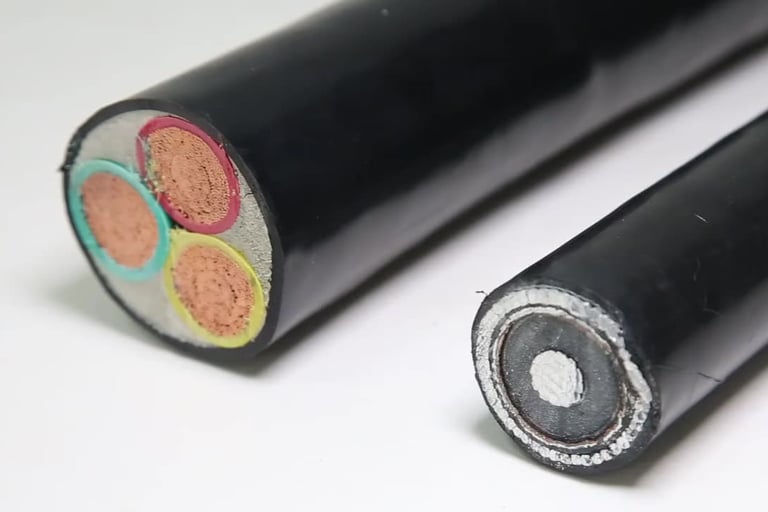
C. Replacing Damaged Wires or Connectors
Replacement Criteria: Replace conductors when cross-sectional area reduction exceeds 20% due to corrosion or mechanical damage. Connectors showing cracking, deformation, or thread damage require immediate replacement regardless of remaining service life.
SANS Compliance Requirements: Ensure replacement components meet SANS 1520-1 specifications for current-carrying capacity and environmental protection. Verify material compatibility with existing system components to prevent galvanic corrosion.
Use connection methods that provide gas-tight joints and maintain contact pressure over the expected service life. Document component specifications and installation details for future maintenance reference.
D. Complete Ground Wire Replacement
When Replacement is Indicated: Complete replacement becomes necessary when diagnostic tests reveal multiple failure points or when conductor integrity is compromised along significant lengths. Cost analysis should consider labour, materials, and downtime factors.
Safety Procedures: Coordinate replacement activities with mine production scheduling to minimise operational impact. Implement comprehensive isolation procedures including mechanical isolation of mobile equipment and verification of zero energy states.
Use temporary grounding systems during replacement activities to maintain personnel safety. Install new grounding conductors using improved routing and support methods to prevent future mechanical damage.
Testing and Documentation: Perform comprehensive electrical testing including continuity, insulation resistance, and load testing before returning systems to service. Document all test results and component specifications for maintenance records.
Underground Mining Cable Special Considerations
Tension and Tie-Point Management
Proper cable support prevents excessive stress at grounding connection points. Implement systematic tie-point spacing based on cable weight and expected dynamic loads. Use appropriate clamps that support cable weight without compressing conductors or damaging sheath materials.
Monitor cable tension during equipment operation using strain gauges or load cells where practical. Maintain tension levels within manufacturer specifications to prevent fatigue damage to grounding conductors.
Mechanical Stress Reduction Strategies
Install cable protection systems in areas subject to rockfall or equipment impact. Use flexible conduits or cable trays that accommodate mining subsidence while protecting cables from mechanical damage.
Implement proper cable routing that minimises sharp bends and provides adequate clearance from moving equipment. Design cable installations with sufficient service loops to accommodate equipment maintenance without imposing stress on connections.
Environmental Protection
Use waterproof connection enclosures in areas subject to water ingress. Implement drainage systems that prevent water accumulation around electrical equipment and cable terminations.
Apply protective coatings appropriate for the specific environmental conditions encountered in each area of the mine. Select materials that maintain effectiveness under temperature cycling and chemical exposure conditions.
Common Tie-Point Errors
Inadequate spacing between support points creates catenary loading that concentrates stress at connection points. Improper clamp installation that doesn't account for thermal expansion can create destructive forces during temperature cycling.
Using support hardware not designed for the specific cable type often results in sheath damage and conductor stress. Failure to account for subsidence effects when designing cable support systems leads to progressive loading that eventually exceeds cable capabilities.
Preventative Maintenance Tips
Regular Inspection and Testing Schedules
Establish inspection frequencies based on environmental severity and equipment criticality. High-priority circuits require monthly visual inspections with quarterly electrical testing. Standard circuits typically require quarterly inspections with annual electrical testing.
Implement trending analysis of test results to identify degrading conditions before failure occurs. Use portable test equipment calibrated to mine standards for consistent measurement accuracy.
Corrosion-Resistant Components
Specify stainless steel or bronze hardware for connections in corrosive environments. Use marine-grade electrical components where moisture exposure is unavoidable.
Apply protective coatings that prevent corrosion initiation while maintaining electrical conductivity at contact surfaces. Select materials with proven performance records in mining applications.
Cable Routing and Support
Design cable installations with adequate service loops and strain relief to accommodate equipment movement and maintenance activities. Use professional cable pulling techniques that prevent conductor damage during installation.
Implement cable marking and documentation systems that facilitate future maintenance and modification work. Maintain current drawings that reflect actual installation conditions.
Training and Standards
Provide comprehensive training for maintenance personnel on grounding system requirements and repair procedures. Ensure training covers both theoretical principles and practical troubleshooting techniques.
Maintain current copies of relevant standards including SANS 1520-1 and manufacturer installation instructions. Implement quality control procedures that verify compliance with installation standards.
Regulatory Standards and Compliance
SANS 1520-1 Grounding Standards
SANS 1520-1 specifies minimum requirements for earthing conductor sizing, installation methods, and testing procedures. Compliance verification requires documentation of conductor sizing calculations and installation inspection records.
The standard addresses specific mining industry requirements including mobile equipment grounding and temporary installation procedures. Regular updates to the standard require ongoing training to maintain compliance.
NRCS Requirements for Cable Repairs
The National Regulator for Compulsory Specifications requires that cable modifications maintain original safety certifications. Repair procedures must follow manufacturer specifications and use approved materials and methods.
Documentation requirements include test certificates and component specifications that demonstrate continued compliance with safety standards. Non-compliance can result in equipment operation restrictions and regulatory penalties.
Mining Safety Audits
Regular safety audits verify compliance with electrical safety regulations and company safety management systems. Grounding system documentation must demonstrate systematic maintenance and testing programmes.
Audit findings often identify systemic issues that require comprehensive corrective actions across multiple installations. Proactive compliance management reduces regulatory exposure and improves overall safety performance.
Real-World Case Study: Platinum Mine Grounding Failure
Incident Background
A recent incident at a major platinum mining operation in the Bushveld Complex highlighted the critical importance of proper grounding system maintenance. The mine experienced repeated earth leakage protection trips affecting a primary ventilation fan installation, threatening production continuity during peak demand periods.
Initial investigations revealed intermittent grounding problems that affected the reliability of protection systems designed to ensure personnel safety in underground workings. The facility management recognised that continued operation with compromised grounding could expose personnel to electrical hazards while potentially violating mine safety regulations.
Diagnostic Process
The maintenance team implemented a systematic diagnostic approach beginning with comprehensive visual inspection of all accessible grounding connections. They discovered significant corrosion at multiple termination points, particularly where copper grounding conductors connected to steel equipment frames.
Electrical testing revealed elevated earth loop impedance values that exceeded SANS 1520-1 requirements for the installation. Further investigation using thermal imaging identified hot spots at connection points, indicating high-resistance joints that posed fire hazards.
Resolution Strategy
The repair programme addressed both immediate safety concerns and long-term reliability improvements. Immediate actions included replacement of severely corroded connections and implementation of temporary grounding systems to maintain safety during repair activities.
Long-term improvements included upgrading to stainless steel connection hardware and implementing systematic inspection procedures based on environmental severity. The maintenance team installed monitoring equipment to trend grounding system performance and identify developing problems before failure occurs.
Lessons Learned
The incident demonstrated the importance of proactive maintenance programmes that address environmental factors specific to mining operations. Regular training for maintenance personnel proved essential for early identification of grounding problems before they compromise safety systems.
Documentation of repair procedures and test results provided valuable information for improving maintenance practices across similar installations throughout the mining complex. The systematic approach to problem resolution minimised operational disruption while ensuring compliance with safety regulations.
FAQ – Frequently Asked Questions
Q: How often should mining cable grounding connections be tested?
A: Testing frequency depends on environmental conditions and equipment criticality. High-priority installations in severe environments require monthly testing, whilst standard installations typically need quarterly testing with annual comprehensive evaluation.
Q: What are acceptable resistance values for mining cable grounding connections?
A: SANS 1520-1 specifies maximum earth loop impedance values based on protection device settings and installation conditions. Generally, grounding conductor resistance should not exceed 1 ohm for equipment grounding and 0.5 ohms for sensitive electronic equipment.
Q: Can temporary grounding connections be used during repairs?
A: Temporary grounding systems are acceptable during maintenance activities provided they meet the same safety requirements as permanent installations. All temporary connections must be properly sized, installed, and tested before placing equipment back in service.
Q: What documentation is required for grounding system repairs?
A: Documentation must include repair procedures used, component specifications, test results, and compliance verification with applicable standards. Maintenance records should demonstrate systematic inspection and testing programmes.
Q: How do you prevent galvanic corrosion in grounding connections?
A: Use compatible metals in connection assemblies and apply protective coatings to prevent moisture ingress. Install isolation joints where dissimilar metals must be connected, and implement systematic inspection programmes to detect early corrosion signs.
Effective maintenance of mining cable grounding connections requires a comprehensive understanding of the unique challenges present in South African mining operations. The combination of harsh environmental conditions, mechanical stresses, and regulatory requirements demands systematic approaches to both preventative maintenance and corrective repairs.
Success in maintaining reliable grounding systems depends on implementing appropriate diagnostic procedures, using proper repair techniques, and establishing preventative maintenance programmes tailored to specific operational conditions. The integration of regulatory compliance requirements with practical maintenance considerations ensures both safety and operational reliability.
The mining industry's continued focus on electrical safety, driven by regulatory requirements and operational necessity, makes grounding system maintenance a critical competency for maintenance personnel. Investment in proper training, quality components, and systematic maintenance procedures provides long-term benefits through reduced downtime, improved safety performance, and regulatory compliance.
By following the procedures outlined in this guide and adapting them to specific operational conditions, mining operations can maintain reliable grounding systems that protect both personnel and equipment while supporting productive mining activities. The key to success lies in understanding that grounding system maintenance is an ongoing process requiring consistent attention and systematic implementation of proven practices.
Email Address: Li.wang@feichuncables.com
© 2025. All rights reserved.
One-click to Quickly Contact
Products
Contact
Company
Location:
Building A Private Science and Technology Park, Hefei Economic and Technological Development Zone, Anhui Province, China
Heat Resistant Cable
WhatsApp: +86 17333223430
Social Media: