Anhui Feichun Special Cable Co.,Ltd Email: Li.wang@feichuncables.com

PANZERFLEX‑L 0.6/1 kV (N)SHTÖU‑JZ/‑OZ Rubber Reeling & Festoon Cables for South African Ports: Engineering Guide for STS Cranes, Stacker Reclaimers and High‑Speed Cable Reel Systems
Engineers, procurement specialists, and maintenance teams operating across South Africa’s major ports and materials handling hubs face unique challenges when selecting flexible control cables. This detailed engineering guide explores PANZERFLEX‑L 0.6/1 kV (N)SHTÖU‑JZ/‑OZ, a rubber cable designed specifically for reeling and festoon systems. Covering technical specifications, material science, performance characteristics, and real‑world application advice tailored for terminals in Durban, Cape Town, Richards Bay, and Saldanha Bay, this article explains why this cable has become the preferred choice for ship‑to‑shore cranes, stacker reclaimers, grab unloaders, and high‑speed moving machinery. It provides accurate data directly from the manufacturer’s documentation, alongside practical insights to assist in specification, installation, and long‑term reliability.
Li Wang
5/15/202624 min read

Introduction
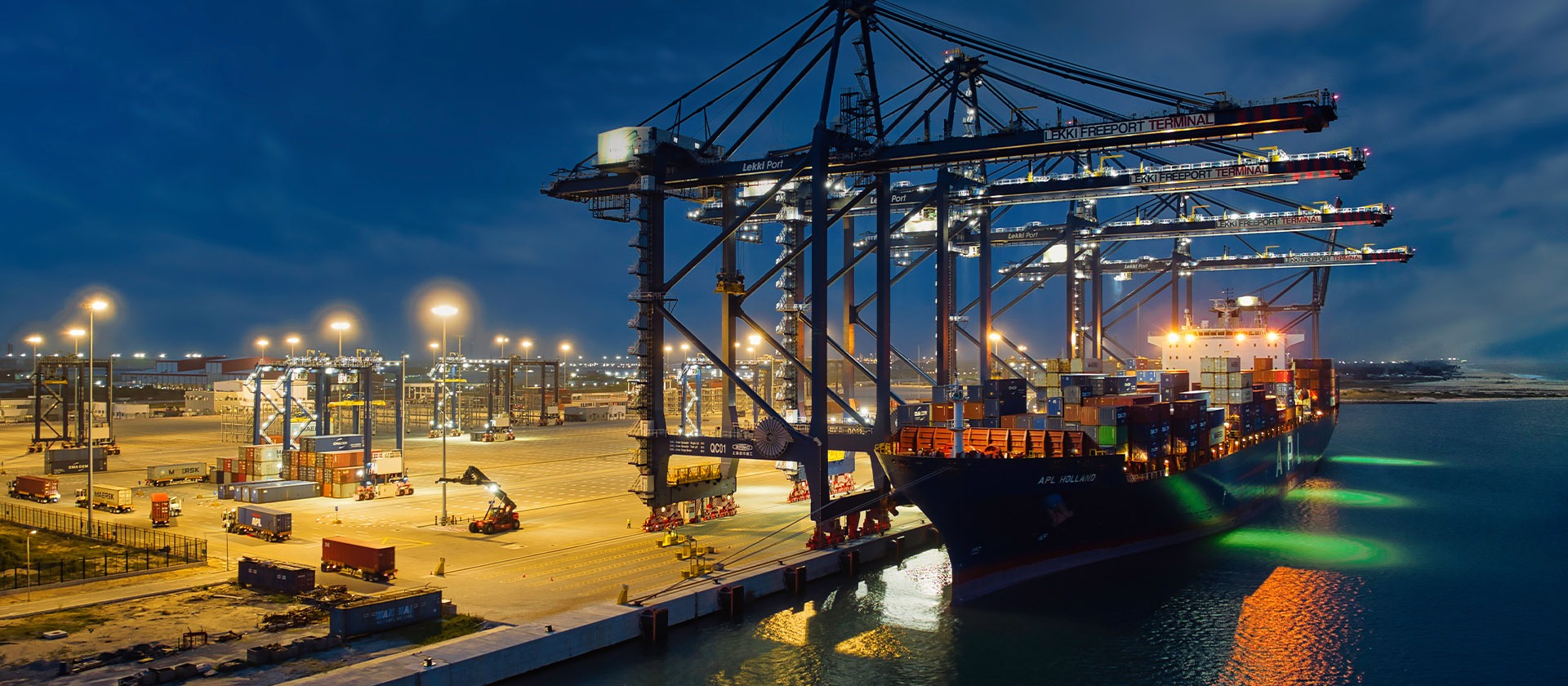
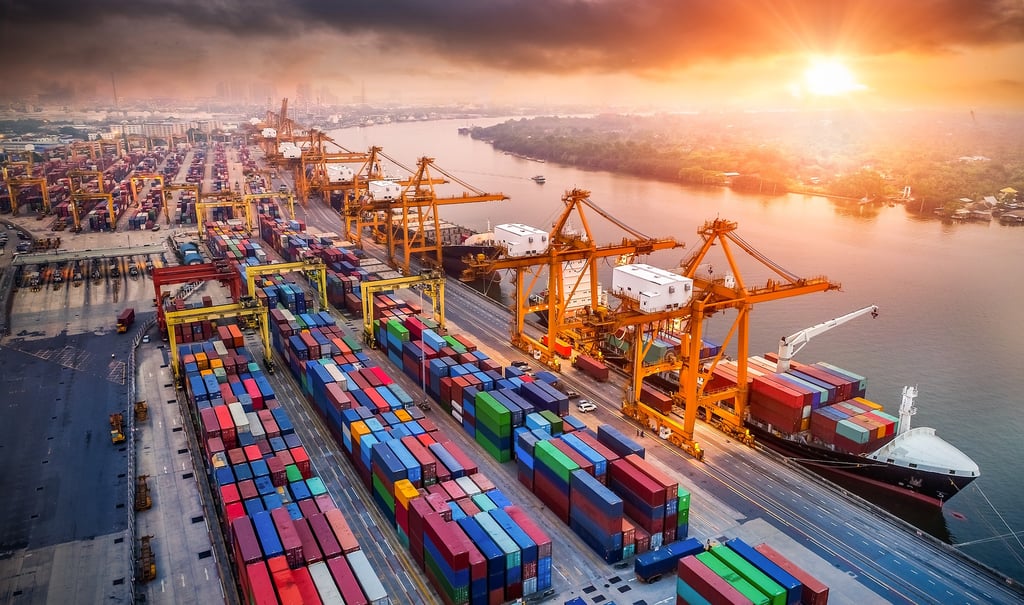
South Africa’s economy relies heavily on the efficiency of its logistics and bulk materials handling infrastructure. From the coal export terminals of Richards Bay to the container hubs of Durban and Cape Town, and the iron ore facilities at Saldanha Bay, equipment operates around the clock in some of the most demanding conditions imaginable. Machines such as ship‑to‑shore cranes, stacker reclaimers, grab‑type unloaders, and gantry cranes are central to these operations. For these systems to function safely and reliably, every component must be engineered to withstand extreme mechanical stress, continuous motion, and aggressive environmental exposure.
Among the most critical yet often under‑specified components are the flexible control cables that carry power, signals, and data to moving parts. Unlike fixed installations, cables used in reeling drums and festoon tracks are subjected to repeated bending, twisting, tensile load, and high‑speed acceleration. In coastal South Africa, they must also resist salt‑laden air, intense ultraviolet radiation, wide temperature variations, and contact with oils, dust, and chemicals. Standard rubber cables or PVC‑sheathed alternatives typically fail within months due to conductor breakage, insulation cracking, or sheath degradation, leading to costly downtime and safety risks.
PANZERFLEX‑L 0.6/1 kV (N)SHTÖU‑JZ/‑OZ represents a solution engineered specifically to address these exact challenges. Manufactured to VDE 0250 Part 814 standards, this range of rubber flexible control cables has been developed with a deep understanding of the operating realities found in South African ports, mines, and industrial terminals. This guide explains the design principles, construction details, and performance capabilities of the cable, drawing entirely on official technical data and practical engineering experience. It is written to support technical professionals in making informed decisions that improve operational reliability and reduce total cost of ownership.
Operating Conditions of Material Handling Equipment in South Africa
To understand why PANZERFLEX‑L is designed the way it is, it is essential to first examine the environment and operational cycles it must survive. Across South Africa’s ports and bulk handling sites, equipment does not simply move; it works under heavy dynamic loads in conditions that test every material limit.
Equipment Types and Operational Profiles
Ship‑to‑shore (STS) cranes, often referred to as quay cranes, are the workhorses of container terminals in Durban and Cape Town. These machines travel along the quay while their booms and trolleys move containers between ship and shore. The cables here move in three axes simultaneously — travelling, traversing, and lifting — creating complex combinations of bending, torsion, and tension. Speeds in modern terminals can reach up to 180 metres per minute or more, with rapid acceleration and deceleration cycles occurring hundreds of times daily.
Stacker reclaimers found at Richards Bay Coal Terminal or iron ore terminals in Saldanha Bay operate over even longer distances. These machines travel along stockyards hundreds of metres in length, while their booms luff and slew to build or reclaim stockpiles. Cables are wound onto large‑diameter drums or guided along long festoon tracks. They are exposed continuously to wind‑blown dust, abrasive particles, and direct sunlight. The repeated winding and unwinding creates significant tensile stress, often sustained for hours at a time.
Grab‑type ship unloaders, used for handling coal, ore, or grain, present an even more severe duty cycle. The grab itself moves vertically and horizontally with high impact loads, while the cable management system must accommodate sudden changes in direction and speed. These cables frequently come into contact with hydraulic oils, grease, and moisture, while also enduring the mechanical shock of grab operation.
Festoon systems, whether for gantry cranes, timber cranes, or transfer carts, are another common application. In these setups, cables hang in loops from trolleys running along a track. As the machine moves, the loops open and close, subjecting the cable to constant bending and twisting. In South Africa, these systems are often installed outdoors with no additional shelter, meaning cables are exposed to rain, high humidity, and extreme temperatures ranging from hot summer days to cold winter nights in inland or high‑altitude locations.
Mechanical and Dynamic Loads
From an engineering perspective, the demands placed on the cable fall into several distinct categories. Tensile load is perhaps the most critical. As the cable is pulled or suspended, it must support its own weight plus any additional forces from acceleration or wind. In heavy‑duty applications, forces can reach up to 15 Newtons per square millimetre of conductor cross‑section. If a cable is not constructed to handle this, conductors will stretch or break, leading to immediate failure.
Bending is continuous. Whether around a drum or along a festoon track, the cable must flex repeatedly over radii that can be as small as 7.5 times the cable’s overall diameter. Over its service life, a cable may undergo millions of bending cycles. Each cycle places stress on the conductor strands, the insulation layers, and the outer sheath. Materials that are too rigid will crack; materials that lack internal support will deform or separate.
Torsion — twisting along the cable’s length — is an often overlooked but highly damaging factor. As a cable unwinds from a drum or moves along a curved path, it naturally twists. If the construction does not resist or absorb this rotation, internal components shift and rub against each other, causing wear and eventual breakage.
Speed and acceleration further compound these issues. In high‑performance terminals, festoon systems operate reliably at speeds up to 240 metres per minute. At these velocities, even minor irregularities in cable construction or material properties can lead to vibration, uneven loading, and accelerated wear.
Environmental Conditions Unique to South Africa
The physical loads are challenging enough, but the South African environment adds another layer of complexity. Coastal locations such as Durban harbour have high levels of salinity in the air. Salt crystals deposited on the cable surface are hygroscopic, attracting moisture and creating an aggressive electrolyte that accelerates corrosion, particularly of metallic components. Ultraviolet radiation is another major factor. South Africa has some of the highest levels of solar irradiance in the world. Standard rubber compounds degrade rapidly under this exposure, becoming brittle, cracking, or losing mechanical strength within just a few years.
Temperature ranges are equally demanding. Along the coast, conditions are relatively mild but humid, typically between -5 °C and +40 °C. However, inland sites, high‑altitude locations, and winter operations can see temperatures drop as low as -25 °C, and in some specialised cases down to -40 °C. A cable that remains flexible at high temperatures but becomes stiff or brittle at low temperatures will fail in service. Conversely, materials that stay flexible in the cold may soften too much in the heat, leading to deformation under load.
Chemical exposure is also common. Hydraulic fluids, lubricating oils, greases, and cleaning agents are present in abundance around machinery. Dust from coal, ore, or grain is abrasive and can work its way into any gap or crack, acting as a grinding compound that wears away protective layers.
Consequences of Inadequate Specification
When cables are selected without fully accounting for these conditions, the results are predictable. Common failure modes include conductor breakage leading to loss of signal or power, insulation breakdown causing short circuits or earth faults, sheath rupture exposing internal components, and core separation where individual conductors pull apart from the assembly. In operational terms, this means unplanned downtime, which in a major port can cost hundreds of thousands of Rands per hour in lost productivity. There are also safety implications, as damaged cables present risks of electric shock or fire.
PANZERFLEX‑L was developed specifically to meet this exact combination of mechanical, dynamic, and environmental challenges found in South African materials handling. Every element of its construction has been chosen and engineered to provide long life and reliable performance in these applications.
PANZERFLEX‑L 0.6/1 kV (N)SHTÖU‑JZ/‑OZ
The following section details the full technical specification of PANZERFLEX‑L 0.6/1 kV (N)SHTÖU‑JZ/‑OZ, drawn directly from the manufacturer’s official documentation and aligned with VDE 0250 Part 814 standards. All data points and construction details correspond exactly to the product catalogue provided.
Definition and Standards
Definition & Identification
PANZERFLEX‑L 0.6/1 kV belongs to a series of flexible control cables, with two main designations: (N)SHTÖU‑JZ and (N)SHTÖU‑OZ.
Key difference: presence or absence of a protective conductor core.
‑JZ: includes a green‑yellow coloured earth/protective conductor.
‑OZ: manufactured without a protective conductor core.
Manufacturing Standards & Compliance
Main standard: VDE 0250 Part 814 — specification for rubber‑insulated flexible cables designed for reeling and trailing use; ensures consistent quality, safety and interchangeability.
Conductor design: complies with IEC 60228, requirements for Class 5 flexible conductors.
Mechanical performance: tested and validated according to DIN VDE 0298‑3 and DIN VDE 0298‑4.
Intended Applications & Operating Conditions
Designed for flexible connection to moving components on machinery and materials handling equipment.
Typical listed equipment:
Stacker reclaimers
Ship‑to‑shore cranes
Container cranes
Festoon systems
Grab unloaders
Gantry festoon systems
Timber crane festoon systems
Functional use: signalling circuits and auxiliary power supply.
Suitable operating environments:
Cable reels and festoon systems
High mechanical stress conditions
Frequent bending and torsional movement
High‑speed travel with strong acceleration/deceleration cycles
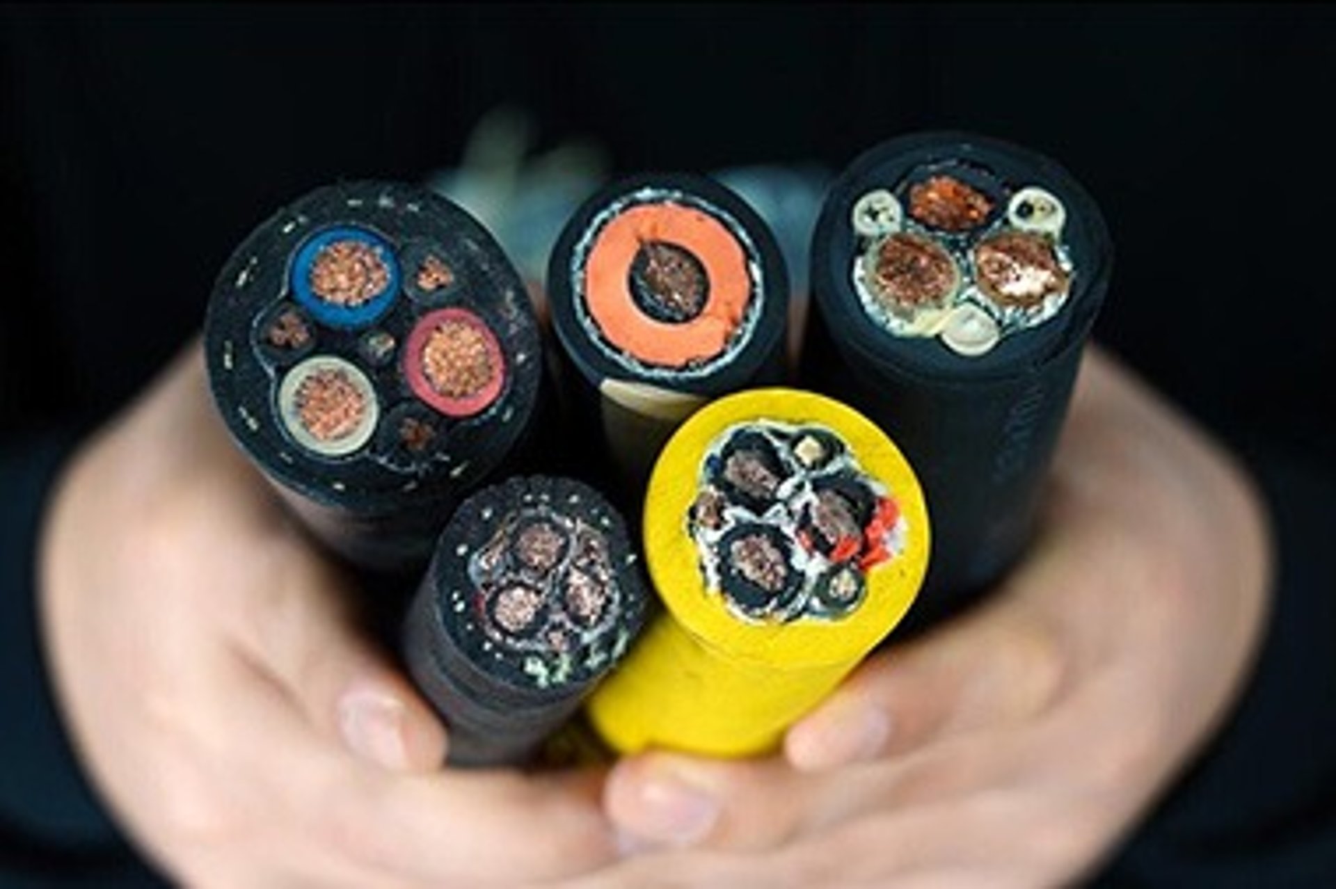
Detailed Construction
The construction of PANZERFLEX‑L is multi‑layered, with each component designed to fulfil a specific function. The assembly is engineered as a system where every element works in harmony to achieve the required performance.
Conductor
Material: tinned copper, offering excellent corrosion resistance suitable for humid and saline environments.
Structure: Class 5 flexible stranding per IEC 60228, made of numerous fine wires in layers to balance flexibility, conductivity and tensile strength.
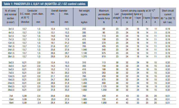
Standard cross‑sections: 1.5 mm², 2.5 mm², 4 mm².
DC resistance at 20 °C: 13.7 Ω/km (1.5 mm²), 8.21 Ω/km (2.5 mm²), 5.09 Ω/km (4 mm²), ensuring efficient current transmission.
Insulation
Material: high‑performance ethylene‑propylene rubber (HEPR), exceeding 3GI3 grade requirements and outperforming standard EPR or rubber compounds.
Properties: crush‑resistant, not easily deformed under radial pressure, with superior electrical and mechanical performance.
Design: thickness optimised for high dielectric strength while keeping cable diameter compact.
Temperature rating: continuous operation at 90 °C; short‑circuit withstand up to 250 °C for max. 5 seconds.
Core Identification System
Design: all cores are black with continuous sequential white number printing from 1 upwards, clear and distinguishable even with up to 36 cores.
Protective conductor: where included, the green‑yellow core is placed in the outer layer for easy visual recognition and structural stability.
Benefit: simplifies installation, maintenance and fault location.
Core Laying‑Up
Lay length: very short, ≤ 7.5 × diameter of the cored bundle, significantly improving flexibility and stress absorption during bending.
Layer limit: maximum three layers, balancing flexibility, diameter and mechanical stability and avoiding excessive stiffness.
Optional: separator tape may be applied to secure the assembly.
Inner Sheath
Material: polychloroprene‑based rubber compound, performance above GM1b standard.
Functions: cushions internal cores, fills gaps to form a round stable structure; adds protection against moisture and chemicals; serves as bonding base for the anti‑twist layer.
Anti‑Twist Protection Layer
Material: high‑strength synthetic yarns.
Structure: applied in a specific helical pattern and firmly bonded to both inner and outer sheaths, preventing relative movement between layers.
Function: absorbs and distributes torsional stress, preventing rotational fatigue and protecting conductors and insulation from twisting damage.
Outer Sheath
Material: black polychloroprene rubber compound, performance exceeding 5GM2 grade — the benchmark for heavy‑duty rubber sheaths.
Features: natural resistance to UV radiation, ozone, weathering, oils and chemicals; carbon black additive provides strong UV stabilisation.
Mechanical properties: tough, highly abrasion‑resistant, flexible over a wide temperature range.
Standard temperature range: –25 °C to +40 °C.
Low‑temperature variant: PANZERFLEX‑L‑K for use down to –40 °C; note this version has slightly lower abrasion and tear resistance.
Key Electrical Parameters
Application & Voltage Ratings
Designed for low‑voltage control circuits and auxiliary power supply systems.
Rated voltage: U₀/U = 0.6/1 kV (600 V between conductor and earth; 1000 V between conductors).
Maximum permitted operating voltage in AC systems: 1.2 kV.
Electrical Quality & Performance
Withstand voltage test: 3.5 kV AC applied for 5 minutes to verify dielectric strength and insulation integrity.
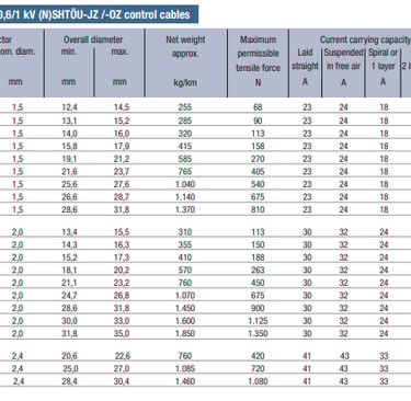
Current‑carrying capacity: specified per DIN VDE 0298 Part 4; values depend on installation method (straight, suspended, spiralled, free air) and number of layers.
Reference values at 30 °C ambient, single loaded core:
1.5 mm²: approx. 23 A
2.5 mm²: approx. 30 A
4 mm²: approx. 41 A
Derating factors must be applied when multiple cores are loaded simultaneously — details available in manufacturer documentation.
Short‑Circuit Characteristics
Based on 1‑second current rating, with conductor temperature rising from 80 °C to 200 °C.
Short‑circuit current values:
1.5 mm²: 0.19 kA
2.5 mm²: 0.32 kA
4 mm²: 0.51 kA
Ensures safe performance and no damage under fault conditions.
Mechanical Performance Characteristics
Tensile Strength Characteristics
Standard rating: maximum permissible tensile load of 15 N/mm², calculated specifically for multi‑core control cable construction.
Design rationale: balances strength, flexibility and structural stability — ideal for reeling and festoon duties; lower than power cable ratings of 20 N/mm² to preserve flexibility.
High‑strength variant: PANZERFLEX‑L‑VS available for long spans or heavy vertical loads; includes central Kevlar® strength member for significantly higher tensile capacity.
Bending Performance
Standard: defined according to DIN VDE 0298‑3.
Minimum bending radius during movement: 7.5 × overall diameter.
Minimum bending radius for fixed installation or storage: 4 × overall diameter — allows tight bending without damage.
Operating Speed Capabilities
Reeling drum systems: no strict speed limit within mechanical capabilities; consultation with manufacturer recommended above 180 m/min to verify drum diameter, tension control and installation details.
Festoon systems: fully tested and certified for continuous operation up to 240 m/min — industry‑leading performance suitable for high‑speed terminals and automated stockyards in South Africa.
Chemical and Environmental Resistance
Chemical Resistance
Offers excellent resistance to chemicals and environmental substances commonly found in port environments.
Oil resistance meets or exceeds VDE and IEC standards; no significant degradation, swelling, or loss of performance when exposed to mineral oils, hydraulic fluids, greases, and lubricants.
Weather and Environmental Resistance
Suitable for unrestricted use in both indoor and outdoor applications.
HEPR insulation and polychloroprene sheath provide inherent resistance to ozone, oxygen, and moisture ingress.
Outer sheath compound includes carbon black to effectively block ultraviolet radiation; prevents polymer degradation even under long‑term exposure to intense sunlight in Southern Africa.
Maintains mechanical properties and appearance over decades; does not become brittle or crack like unprotected rubber or PVC materials.
Technical Specification Table
Deep‑Dive into Core Technologies and Engineering Principles
While the construction details explain what the cable is made of, understanding why these materials and designs were chosen provides valuable insight for specification and application. Every element of PANZERFLEX‑L is rooted in material science and mechanical engineering principles designed to solve specific problems found in South African ports.
HEPR Insulation Chemistry: Elastomer Science and Electrical Stability
Insulation is the first line of defence, and the choice of HEPR — High‑Performance Ethylene‑Propylene Rubber — is one of the most critical design decisions. Standard EPR (Ethylene‑Propylene Rubber) is widely used, but HEPR represents a significant evolution in polymer formulation and cross‑linking technology.
Chemically, HEPR is a saturated elastomer. Unlike natural rubber or styrene‑butadiene rubber, it contains no carbon‑carbon double bonds in its main molecular chain. This saturation is the fundamental reason for its exceptional resistance to ageing, heat, and ozone. Ozone, formed by sunlight acting on oxygen, is highly aggressive and is the primary cause of cracking in outdoor rubber products. Because HEPR has no reactive sites in its structure, ozone cannot attack or degrade it, even in the high‑ozone environments common near large bodies of water like Durban Harbour.
The polymer chains are cross‑linked during manufacturing to create a three‑dimensional network. This network structure provides a balance of properties that thermoplastics like PVC simply cannot achieve. It allows the material to remain flexible at low temperatures while resisting deformation at high temperatures. Unlike thermoplastics, which soften and flow when heated, cross‑linked elastomers retain their shape and mechanical integrity. This is essential in reeling applications where the insulation must maintain uniform thickness and electrical properties under pressure and heat.
From an electrical perspective, HEPR is nearly ideal. It has a very low dielectric constant and a low dissipation factor, meaning it does not store electrical energy or generate heat when subjected to alternating current. This stability ensures that insulation resistance remains high and consistent, even under humid or wet conditions. In practical terms, this translates to fewer insulation‑related faults and reliable signal transmission, which is vital for the precise control systems used on modern cranes.
Furthermore, the specific formulation used in PANZERFLEX‑L exceeds the requirements of the 3GI3 standard. This grade is defined by its excellent mechanical properties, specifically high resistance to crushing and abrasion. When a cable is wound tightly onto a drum or compressed between trolleys in a festoon system, the insulation must not deform or flow. HEPR maintains its structure under these loads, preventing the conductor from moving off‑centre and ensuring consistent electrical performance over the entire service life.
Numbered Multi‑Core Identification: Design Architecture and Wiring Simplification
As control systems become more complex, the number of cores required in a single cable increases. Cables with 12, 24, or even 36 cores are now standard in automated terminals. Traditional colour‑coding systems quickly become impractical or impossible at these core counts, as the number of distinct colours and colour combinations is limited.
The solution implemented in PANZERFLEX‑L is a numbered identification system. Every insulated core is black and marked with a continuous white numerical print, starting from 1 upwards. This system is logical, scalable, and unambiguous. Regardless of whether the cable has 5 cores or 35 cores, each one has a unique identifier.
This design architecture offers significant advantages in the field, particularly in South African operations where speed and accuracy during installation and maintenance are paramount. During initial wiring, technicians can follow documentation exactly, connecting core number n to terminal n without confusion or the need to interpret complex colour codes. During maintenance or fault‑finding, identifying a damaged or failed core is as simple as reading the number printed on it. This reduces the time required to locate and rectify faults, directly minimising costly downtime.
Placing the green‑yellow protective conductor in the outer layer is another thoughtful engineering detail. This position ensures the earth core is always visible and easily distinguishable, further simplifying safety checks and earthing continuity tests.
The printing itself is formulated to resist abrasion, solvents, and heat. It remains legible for the life of the cable, even after thousands of bending cycles and exposure to oils and cleaning agents. This attention to detail supports the entire lifecycle of the equipment, from commissioning through decades of service.
Black Polychloroprene (PCP) 5GM2‑Grade Sheath: Durability for Port Environments
The outer sheath is the armour of the cable. It faces the environment directly, and in port applications, it faces the harshest conditions possible. The choice of black polychloroprene rubber compound exceeding 5GM2 grade is the result of decades of experience in heavy‑duty applications.
Polychloroprene — often known by the trade name Neoprene — is a synthetic rubber that combines mechanical toughness with excellent resistance to weathering, oils, and chemicals. Its chemical structure includes chlorine atoms attached to the polymer chain. This modification makes the material far less permeable to gases, water vapour, and oils than hydrocarbon rubbers. In practice, this means moisture from the humid coastal air or hydraulic oil spilled during maintenance cannot easily penetrate the sheath to attack the underlying layers.
The 5GM2 designation is a VDE standard defining the performance level of sheath compounds. To meet or exceed this standard, the material must pass rigorous tests for tensile strength, elongation at break, tear resistance, abrasion resistance, and resistance to ageing in air and oil. The compound used here surpasses these minimum requirements, providing a safety margin essential for 24/7 operation.
The black colouration is achieved by incorporating high‑structure carbon black into the polymer matrix. Carbon black is one of the most effective UV stabilisers available. It absorbs ultraviolet radiation and dissipates it as harmless heat, preventing the energy from breaking the chemical bonds in the rubber. In South Africa, where solar irradiance is intense, this feature is non‑negotiable. Without it, a rubber sheath would become brittle and crack within a few years, exposing the cable core to the elements.
Mechanically, this sheath is tough enough to withstand the friction of festoon rollers, the pressure of drum flanges, and the impact of debris or handling. It resists cutting and tearing, yet remains flexible enough to bend easily. It strikes a perfect balance — hard‑wearing on the outside, yet flexible and protective on the inside.
For specialised applications requiring operation down to -40 °C, the ‑K variant uses a modified polymer blend. While this formulation improves low‑temperature flexibility, it inherently trades off some abrasion and tear resistance. This compromise is a necessary physical limitation of polymer science, and the manufacturer is transparent about it, ensuring engineers understand that while the cable works in extreme cold, care must be taken regarding mechanical wear.
Anti‑Twist Synthetic Yarn Structure: Rotational Fatigue Mitigation
One of the leading causes of failure in reeling cables is not bending or tension, but torsion — twisting. When a cable is wound onto a drum, particularly if the drum is not perfectly aligned or the cable is guided over sheaves, it naturally rotates along its axis. Over time, this repeated twisting causes internal stress. In standard cables, this stress leads to the cores spiralling or bunching up, rubbing against each other and the sheath until insulation wears through or conductors snap.
PANZERFLEX‑L addresses this with a dedicated anti‑twist protection layer made from synthetic yarns, firmly bonded between the inner and outer sheaths. This is not simply a layer of tape or loose fibres; it is a structural element integrated into the cable design.
The synthetic yarns used have very high tensile strength and low elongation. They are applied in a helical pattern that creates a cylindrical cage around the core assembly. Because this layer is bonded securely to both inner and outer sheaths, it cannot slide or rotate independently. When the cable is subjected to twisting forces, this layer absorbs the torque and distributes it evenly around the circumference. It acts like a torque tube, keeping the internal core assembly stable and preventing it from rotating relative to the outside surface.
This design effectively isolates the conductors and insulation from rotational stress. They remain in their designed positions, maintaining their lay and geometry even as the cable twists as a whole. The result is a dramatic reduction in internal friction and fatigue. In field tests and real‑world operation, this feature alone has been shown to double or triple the service life of the cable compared to standard designs. It is arguably the single most important engineering innovation that makes PANZERFLEX‑L suitable for the demanding high‑speed reeling and festoon systems found in South African ports.
Flexible Reeling and Festoon‑Optimised Design: 240 m/min Capability and Mechanical Integrity
Every aspect of the cable’s construction — from the fine‑wire stranding of the conductor to the short lay‑up of the cores and the balanced sheath design — is optimised for flexibility without compromising mechanical strength.
Flexibility is achieved through geometry as much as through material choice. By stranding conductors with fine wires and cabling them together with a very short lay length (maximum 7.5 times the bundle diameter), the bending radius of the cable is minimised. In a flexible structure, individual elements slide or rotate slightly during bending to accommodate the change in length between the inner and outer radii of the bend. The short lay‑up ensures that these adjustments happen smoothly and with low internal stress.
Limiting the assembly to a maximum of three layers is another optimisation. Multi‑core cables with many layers become progressively stiffer and less balanced as the diameter increases. By keeping the construction compact and symmetrical, PANZERFLEX‑L maintains consistent bending characteristics in all directions. This symmetry is essential for high‑speed operation, where uneven flexibility could lead to vibration or whip‑lash.
The result of these design choices is a cable capable of operating reliably at speeds up to 240 metres per minute in festoon systems. This is a benchmark performance level. At such high speeds, even minor imperfections or stiff sections would lead to accelerated wear or failure. The fact that PANZERFLEX‑L is certified for this speed demonstrates the precision of its engineering. It is designed to move fast, bend tight, twist repeatedly, and carry load — all while remaining electrically stable and mechanically sound.
Application Suitability and Specification Guide: Control System Selection
Specifying the correct cable involves matching the product’s capabilities to the specific requirements of the equipment, the operating cycle, and the environment. This section provides a practical guide for engineers and procurement professionals working in South African terminals.
Matching Cable to Equipment Type
Different machines impose different demands, and selecting the right configuration optimises both performance and cost.
Ship‑to‑Shore (STS) Cranes and Container Cranes require cables with medium‑to‑high core counts to handle the numerous control loops, safety circuits, and communication lines required for automated operation. Speeds are high, often approaching 180–200 m/min, and torsion is significant due to the multi‑axis movement. The recommended choice is **PANZERFLEX‑L with 12 to 24 cores, in either 1.5 mm² or 2.5 mm² cross‑section. The 2.5 mm² size is preferred where auxiliary power circuits are included or where longer runs result in higher voltage drop. The standard black outer sheath is ideal to combat salt spray and intense UV radiation. For installations where temperatures drop below –25 °C during winter months, such as at terminals further inland or at higher elevations, the ‑K low‑temperature variant should be specified to maintain flexibility and prevent sheath cracking.
Stacker Reclaimers and Bulk Handling Machines operate over long distances and experience continuous winding and unwinding on large‑diameter drums. The key requirements here are high tensile strength, excellent abrasion resistance, and resistance to dust and abrasive particles. Core counts typically range from 7 up to 18 cores, depending on the level of automation and feedback systems installed. The 2.5 mm² cross‑section is the most common selection, offering a good balance between current capacity, mechanical strength, and cable diameter. The short lay‑up and anti‑twist construction of PANZERFLEX‑L are particularly valuable here, as they prevent the cable from “corkscrewing” or deforming under the sustained tension and cyclic bending associated with long‑travel machinery.
Grab‑Type Ship Unloaders present one of the harshest duty cycles found in any port environment. The cable is subjected to vertical lifting, horizontal traversing, and the shock loads generated by the grab itself impacting material or the ship’s hold. Oil contamination is high due to proximity to hydraulic systems, and the mechanical wear from dust and debris is severe. Specifications should prioritise mechanical robustness and oil resistance. The recommendation is to use 2.5 mm² or 4 mm² conductors with core counts between 7 and 12. The 4 mm² size provides an additional safety margin for mechanical strength and is often chosen where the cable also supplies power to hydraulic pumps or motors. The outer sheath, exceeding the 5GM2 standard, ensures resistance to hydraulic fluids and abrasion, while the HEPR insulation remains stable despite the heat generated by heavy cyclic loading.
Festoon Systems — Gantry, Timber Crane, and Transfer Cart Applications require cables designed for high‑speed, long‑span horizontal movement. Speeds up to the certified maximum of 240 m/min are common in modern automated yards. The cable must be highly flexible to accommodate the opening and closing loops without fatigue. Core counts are often the highest found in any application, reaching up to 36 cores, to handle the extensive signalling, interlocking, and communication requirements. The selection here focuses on flexibility and high‑speed rating. 1.5 mm² conductors are suitable for pure signal and control circuits, while 2.5 mm² is used where power is also transmitted. The anti‑twist synthetic yarn layer is essential in festoon systems, as it prevents the cable from spiralling or tangling as it moves. Engineers should ensure the festoon trolley spacing and loop length are designed within the cable’s minimum bending radius and tension limits to maximise service life.
Conductor Size Selection Rules
Choosing the correct conductor cross‑section is a balance between electrical performance, mechanical durability, and cost.
1.5 mm² is the smallest standard size offered. It is sufficient for circuits carrying low currents, typically up to 23 Amps under reference conditions. This size is ideal for digital signals, sensors, limit switches, indicator lights, and communication lines. It allows for the highest core counts within a manageable overall diameter and weight, making it the preferred choice for complex control systems where space on the festoon trolley or drum is limited. It is lighter and more flexible than larger sizes, reducing the overall load on the cable management system.
2.5 mm² is widely regarded as the workhorse size for South African ports. With a current‑carrying capacity of approximately 30 Amps, it handles the majority of control circuits, solenoid valves, small motors, and auxiliary power supplies. It offers a significant increase in mechanical strength and tensile load capacity compared to 1.5 mm², without becoming excessively heavy or stiff. For most applications, unless specific calculations dictate otherwise, 2.5 mm² represents the optimal default choice, providing excellent longevity and a safety margin that accounts for future system modifications or unforeseen load changes.
4 mm² is reserved for circuits requiring higher current, up to approximately 41 Amps, or where additional mechanical robustness is required. It is commonly used for power supply to control panels, heating elements, larger drive motors, or where the cable is suspended vertically or over very long distances. While more expensive and heavier, the larger conductor reduces resistance and voltage drop, making it suitable for longer cable runs. It is also inherently more resistant to conductor breakage under high tension or shock loads.
Engineers must also apply derating factors when sizing cables. The current‑carrying capacity values provided in the datasheet assume ideal conditions. When multiple cores within the same cable are loaded simultaneously, heat build‑up increases, and the allowable current per core decreases. DIN VDE 0298‑4 provides detailed tables for these derating factors, and these must be consulted to ensure the cable operates within its thermal limits.
Core Count Logic and Planning
Determining the number of cores requires a detailed analysis of the control schematic, but there are established principles that apply universally.
Core count is determined by the number of circuits required, including power phases, neutral conductors, protective earth, control signals, feedback loops, communication lines, and any auxiliary supplies. It is standard practice in South African industry to include spare cores in the cable specification. These spare cores act as a contingency for future system upgrades, modifications, or in the event of a failure in an active core. A typical rule of thumb is to add 10 % to 20 % to the calculated requirement or specify the next available standard size.
For basic control functions — such as start/stop, forward/reverse, and basic safety interlocks — 7 to 12 cores are usually sufficient.
For automated systems, PLC‑controlled machinery, or cranes with anti‑sway, automation, and multiple feedback systems, core counts of 18 to 24 cores are common.
For large ship‑to‑shore cranes or specialised handling equipment with redundant systems, multiple communication buses, or distributed I/O, the maximum offering of 36 cores may be required.
It is critical to note that PANZERFLEX‑L‑JZ includes the protective earth conductor within the core count. For example, a specification of 7 × 2.5 mm² actually provides 6 power/control cores plus 1 earth core. The ‑OZ version excludes the earth core, which must be accounted for separately in system design or bonding arrangements.
Installation and Operational Best Practices
Even the best‑engineered cable will fail prematurely if installed or operated incorrectly. Adhering to the following guidelines ensures the design life of 10–15 years is achieved.
Bending radius limits are non‑negotiable. During movement, the cable must never be bent to a radius less than 7.5 times the overall diameter. On cable drums, this places a minimum limit on the drum diameter. In festoon systems, this dictates the minimum loop length and trolley spacing. Operating below this limit creates excessive stress on the conductor strands and insulation, leading to accelerated fatigue.
Tension control is equally important. The maximum tensile load of 15 N/mm² must not be exceeded. This requires proper design of the cable reeling drum’s drive system or the tensioning mechanism on festoon systems. Too much tension stretches the conductors, increasing resistance and eventually breaking them. Too little tension causes slack, leading to looping, tangling, or the cable jumping off the drum or track.
Environmental considerations during installation include ensuring that cables are not pulled over sharp edges or abrasive surfaces without protection. Sealing of entry points into control panels or slip‑ring housings prevents dust and moisture ingress at termination points.
Maintenance should include regular visual inspections for signs of wear, cracking, or swelling. Measurement of insulation resistance at regular intervals provides early warning of degradation. In South Africa’s coastal environment, periodic cleaning to remove salt deposits helps maintain the integrity of the outer sheath and prevents surface tracking.
Common Specification Mistakes to Avoid
Experience shows that certain errors recur frequently in cable specification. Avoiding these ensures reliability and reduces costs.
One common mistake is under‑specifying core count or omitting spare cores. When modifications are needed later, running additional cables is expensive and mechanically difficult. Including spare cores from the outset is a minimal extra cost compared to the cost of retrofitting.
Another error is using a power cable (‑M series) for control circuits. This results in a larger, heavier, stiffer, and more expensive installation that is harder to route and less durable in high‑speed festoon applications.
Ignoring temperature ratings is dangerous. Specifying a standard cable for an inland site where winter temperatures drop to –30 °C will result in the sheath becoming brittle and cracking within the first season. Conversely, specifying the low‑temperature ‑K variant for a coastal site where temperatures never drop below –10 °C sacrifices abrasion resistance unnecessarily.
Mixing cable types or generations within the same system can cause uneven wear and tension distribution, leading to premature failure of the weaker component. Standardising on PANZERFLEX‑L across a terminal simplifies inventory, maintenance, and ensures consistent performance.
Frequently Asked Questions
What does the designation ‑JZ and ‑OZ mean?
The suffix ‑JZ indicates the cable includes a green‑yellow coloured protective earth conductor as part of the core count. This is the standard and most commonly supplied version. The suffix ‑OZ designates a version manufactured without the protective earth core. This is used where the equipment or installation method provides an alternative means of earthing or where the earth conductor is run separately.
Is this cable suitable for direct burial or fixed installation?
While the cable is mechanically robust and weather‑resistant, it is designed specifically for flexible, moving applications. Direct burial is not recommended unless additional protection is provided, as the outer sheath is not designed to withstand the point loads or abrasion from soil and stones. For fixed installations, standard rubber or PVC cables are more cost‑effective.
What is the difference between PANZERFLEX‑L and PANZERFLEX‑L‑K?
The standard PANZERFLEX‑L operates reliably from –25 °C up to +40 °C. The ‑K version is formulated with a special rubber compound that extends the low‑temperature limit down to –40 °C. However, this modification results in slightly reduced resistance to abrasion and tearing. It is recommended only for environments where temperatures fall below –25 °C.
Can PANZERFLEX‑L be used in festoon systems running at 240 m/min?
Yes. PANZERFLEX‑L is fully tested and certified for continuous operation at speeds up to 240 m/min in festoon applications. This is one of its key performance advantages and makes it suitable for the fastest automated container handling equipment found in South African ports. For speeds exceeding 180 m/min on cable reels, consultation with the manufacturer is advised to review drum diameter and tension control parameters.
What happens if the tensile load exceeds 15 N/mm²?
Exceeding the rated tensile load of 15 N/mm² will cause permanent elongation of the copper conductors. This increases electrical resistance and leads to work‑hardening of the copper, making it brittle and prone to breaking under subsequent bending cycles. If your application inherently requires higher tension, you should select PANZERFLEX‑L‑VS, which incorporates a central Kevlar® strength member, increasing the tensile rating to over 20 N/mm² while maintaining flexibility.
Does the black colour affect performance?
The black colour is achieved by adding high‑quality carbon black to the outer sheath compound. This is essential for UV stabilisation. Without carbon black, the rubber would degrade rapidly under South Africa’s intense sun. The black colour does not affect electrical performance, as the outer sheath is an insulating layer.
Are these cables compliant with South African standards?
While South Africa has its own SABS standards, the international VDE 0250 Part 814 standard to which PANZERFLEX‑L is manufactured is widely recognised, accepted, and specified by major terminal operators, engineering firms, and port authorities throughout the region. It meets or exceeds the requirements typically found in local specifications for heavy‑duty reeling cables.
Conclusion
The selection of control cables for materials handling equipment in South Africa is not a minor detail; it is a fundamental engineering decision that impacts safety, operational efficiency, and total cost of ownership. The operating environment — characterised by high mechanical stress, continuous motion, salt air, intense UV radiation, and extreme temperatures — places demands that standard cables simply cannot meet.
PANZERFLEX‑L 0.6/1 kV (N)SHTÖU‑JZ/‑OZ has been engineered specifically to meet these challenges. Through the use of advanced materials such as HEPR insulation and 5GM2‑grade polychloroprene, combined with innovative design features like the short lay‑up, numbered core identification, and the proprietary anti‑twist synthetic yarn layer, it addresses every failure mode commonly encountered in port applications.
This guide has detailed the construction, the material science behind it, and the practical application rules derived from years of field experience. It is clear that this cable is not just a commodity product, but a specialised component designed to function as an integral part of the machine it serves. For engineers and procurement professionals in Durban, Cape Town, Richards Bay, Saldanha Bay, and beyond, PANZERFLEX‑L represents a reliable, proven, and technically superior solution. It ensures that the critical signals and power required to move our economy are transmitted safely and reliably, hour after hour, year after year.
If you require further technical data sheets, detailed pricing, or assistance in selecting the correct configuration of PANZERFLEX‑L 0.6/1 kV (N)SHTÖU‑JZ/‑OZ for your specific application or project in South Africa, please contact the Feichun Cable technical and sales team directly at Li.wang@feichuncables.com. Our specialists are ready to provide engineering support, documentation, and delivery arrangements tailored to your requirements.
Email Address: Li.wang@feichuncables.com
© 2025. All rights reserved.

One-click to Quickly Contact
Products
Contact
Company
Location:
Building A Private Science and Technology Park, Hefei Economic and Technological Development Zone, Anhui Province, China
Heat Resistant Cable
WhatsApp: +86 17333223430
Social Media: