Anhui Feichun Special Cable Co.,Ltd Email: Li.wang@feichuncables.com

PROTOLON(SMK)-LWL (N)TSKCGEWOEU: Integrated Medium Voltage Fiber Optic Cable for Automated STS Cranes in South Africa Ports
Discover how PROTOLON(SMK)-LWL (N)TSKCGEWOEU integrated medium voltage fiber optic cables transform operations for Ship-to-Shore (STS) cranes at automated container terminals in South Africa. This comprehensive guide explores the limitations of traditional multi-cable systems, the innovative design and full technical specifications of PROTOLON(SMK)-LWL, in-depth analysis of fiber performance and structural advantages, practical comparisons, deployment strategies, and expert insights. Tailored for port engineers, system integrators, and infrastructure planners looking to enhance reliability, reduce costs, and streamline maintenance in next-generation automated port facilities.
Li Wang
5/8/202629 min read
Introduction: The Evolution of Cabling in Modern Automated Ports
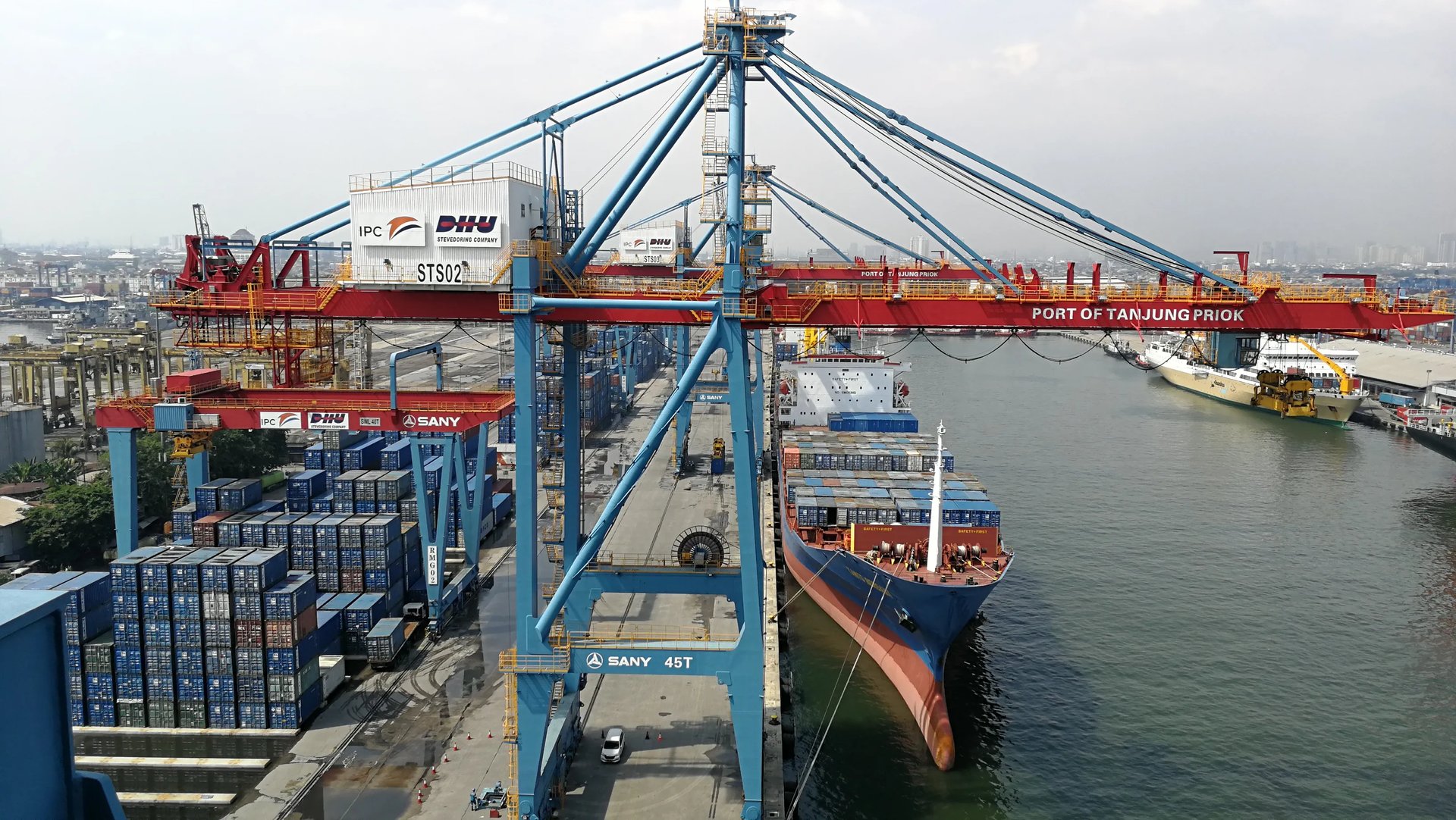
Global trade continues to expand, and with it the demand for faster, safer, and more efficient port operations. Across Africa, South Africa stands out as a key logistics hub, serving as a gateway between international shipping routes and inland economies. In recent years, local port operators have increasingly turned to automation to boost productivity, reduce operational costs, and improve safety standards. At the heart of these automated facilities are Ship-to-Shore (STS) cranes – massive machines responsible for moving containers between vessels and the quay. As these systems become more advanced, the infrastructure required to support them must also evolve, particularly when it comes to cabling solutions.
Modern STS cranes operate under some of the most demanding conditions imaginable. They require a massive amount of electrical power, with peak loads reaching between 18 and 20 megawatts, delivered at voltages of 18 to 30 kilovolts and currents of up to 600 amps. Alongside this high-power supply, these cranes rely on continuous, high-speed data communication to function correctly. Data streams include real-time position feedback, load weight measurements, structural health monitoring, remote control signals, and high-definition video from multiple cameras. All of this information must be transmitted reliably and with very low latency to ensure precise control and safe operation.
The link between the fixed power and communication networks on the shore and the moving crane is the cable system. This critical infrastructure must withstand continuous movement, bending, twisting, tension, and exposure to harsh environmental conditions. For decades, port operators have relied on separate cables for power and data transmission. However, as automation technology has advanced, the limitations of these traditional systems have become increasingly apparent. This article explores these challenges in detail and introduces PROTOLON(SMK)-LWL (N)TSKCGEWOEU, an innovative integrated cable solution designed specifically to meet the rigorous demands of automated STS crane operations in South Africa and around the world.
STS Crane Operations at South African Automated Terminals
How Modern STS Cranes Work
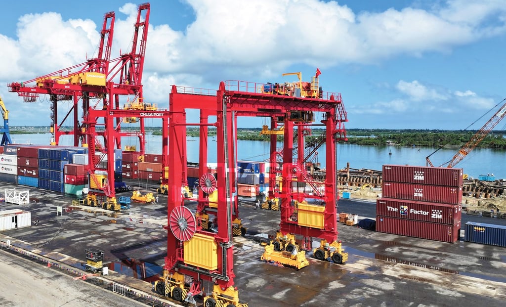
In any container terminal, the STS crane is the primary workhorse. It performs the essential task of transferring containers from ships to the quay, and vice versa. In South Africa’s major ports such as Durban, Cape Town, and Ngqura, these machines have become increasingly sophisticated, with many facilities transitioning from manual operation to semi-automated or fully remote-controlled systems. An automated STS crane consists of several key components working in unison. The main structure includes a tall portal frame that travels along rails on the quay, a horizontal boom that extends over the ship, and a trolley that moves along the boom. A hoist system lowers and raises a spreader – the mechanism that locks onto containers – with extreme precision.
Automation technology coordinates all these movements to optimise the container handling cycle. Advanced sensors continuously monitor the crane’s position, speed, load weight, and structural vibration. Laser scanners and cameras identify container locations and dimensions, while anti-sway systems ensure smooth movement of loads to prevent damage and improve safety. In fully automated terminals, human operators may work from a remote control room kilometres away, relying entirely on data and video transmitted through the cable system to supervise operations and intervene when necessary.
Data and Power Requirements in Detail
To support these complex operations, the cable system must deliver two fundamentally different types of service reliably and simultaneously. On the power side, the system must supply enough energy to drive powerful electric motors, hydraulic pumps, cooling systems, and control electronics. At peak operation, when lifting heavy containers at high speeds or moving large distances, power consumption can reach 20 megawatts. To deliver this power efficiently over the distances involved – often 100 metres or more – medium voltage levels of 18 to 30 kilovolts are used. This requires cables with high-quality insulation and robust electrical performance characteristics.
On the communication side, the requirements are equally demanding but quite different in nature. The data network must support several distinct types of information flow, each with its own specifications. Control signals are the most critical category. These commands direct the movement of the crane and its components and must be transmitted with latency of less than 10 milliseconds and extremely high reliability. Even brief interruptions or delays can cause operational errors or safety incidents. Monitoring data includes measurements from hundreds of sensors distributed throughout the crane structure and machinery. This information helps operators and maintenance teams track equipment health, predict failures, and optimise performance. It requires continuous transmission at moderate data rates. Video feeds from cameras positioned along the boom, trolley, and spreader provide visual information essential for both automatic systems and remote human operators. These streams require high bandwidth to deliver clear images at sufficient frame rates.
Environmental and Mechanical Challenges in South African Ports
South Africa’s coastal environment presents unique challenges for port infrastructure. Most terminals are located in regions with high humidity, strong sunlight, and significant exposure to salt spray. These factors accelerate material degradation, causing corrosion, UV damage, and insulation breakdown over time. Temperatures can vary widely, from near-freezing conditions during winter nights to extreme heat during summer days. The cable system must operate reliably across this entire range without performance loss.
Mechanically, the environment is equally demanding. STS cranes move continuously along the quay, meaning the connecting cable is repeatedly wound onto and off large reels. During operation, the cable undergoes thousands of bending cycles, experiences significant tensile forces, and is subjected to twisting motions as the crane changes direction. It must also resist abrasion from contact with guide rollers, supports, and other equipment. In some cases, cables may be exposed to accidental impacts or contact with spilled fluids such as oils or greases. All these factors combine to create a harsh operating environment that places immense stress on cable materials and construction.
Traditional Cabling Solutions: Architecture, Performance, and Limitations
Standard Electrical Architecture for Automated STS Cranes
For many years, the standard approach to meeting power and communication needs has been to install separate systems for each function. This traditional architecture consists of three distinct cabling systems running in parallel between the shore substation and the crane control room.
The power supply system typically comprises three single-core cables, each with a conductor cross-section of 185 square millimetres, rated for 18 to 30 kilovolts. This configuration is designed to carry the high currents required, up to 600 amps, while maintaining safe electrical performance and insulation integrity. These cables are constructed with robust insulation and protective sheathing, but their primary focus is on electrical performance and mechanical durability.
For control and monitoring signals, operators traditionally use multiple pairs of copper wires bundled into control cables. A common configuration is a 7×1.5 square millimetre shielded twisted pair cable. This type of cable is designed to transmit low-voltage electrical signals representing measurements, commands, and status information. The twisted pair construction and shielding are intended to reduce interference, though their effectiveness is limited in high-voltage environments.
For video transmission and high-speed data exchange, a third separate cable system is installed, usually containing optical fibres. These cables are designed to provide high bandwidth communication but offer no power transmission capability. They are constructed with specialised materials to protect the delicate glass fibres inside.
Infrastructure Requirements for the Three-Cable System
Operating three separate cable systems creates significant infrastructure demands. Since all cables move with the crane, each system requires its own dedicated reel mechanism. This means installing three separate cable drums, drive systems, and tension control mechanisms. These components are large, heavy, and expensive, requiring substantial structural support on both the crane and the shore end.
Each cable system also needs independent routing paths. This involves installing multiple guide rollers, troughs, and support structures to ensure smooth movement and prevent tangling or damage. Because the cables move at slightly different rates and follow different paths, precise alignment and tension control are essential. Termination points present another area of complexity. Each cable system must be connected separately at both ends, requiring multiple junction boxes, connectors, and grounding systems. Installation involves extensive labour and careful coordination to ensure all systems are correctly positioned and connected.
To ensure reliability, operators often install redundant routing paths and spare cables. This adds even more complexity to the infrastructure design, requiring additional space, materials, and maintenance effort.
Key Drawbacks and Operational Impacts
While traditional systems have served the industry well for many years, they come with significant disadvantages that have become increasingly problematic as automation technology advances.
The most obvious issue is complexity. Managing three separate systems increases the potential for failure at every stage, from installation through operation to maintenance. During installation, coordinating the routing and connection of multiple cables is time-consuming and prone to human error. Even minor mistakes can lead to performance issues or premature failure.
Maintenance becomes a major challenge with separate systems. Each type of cable requires different inspection procedures, testing equipment, and maintenance schedules. Technicians must be trained to work on all three systems, and spare parts inventories must cover multiple types of components. When problems occur, identifying which system is affected and locating the fault point takes longer than it would with a unified solution.
Electromagnetic interference presents another significant challenge. High-voltage power cables generate strong electromagnetic fields that can induce noise and interference in nearby copper control cables. Even with shielding, signal quality can degrade over time, leading to measurement errors, control malfunctions, or communication dropouts. This problem becomes more severe as systems operate closer together or as data transmission speeds increase.
Space utilisation is also inefficient. Multiple cables and their associated infrastructure occupy considerable space on the crane structure and along the quay. In many South African ports, terminal space is at a premium, and reducing the footprint of infrastructure can free up valuable operational area.
Perhaps most importantly, traditional systems limit future flexibility. As automation technology evolves, operators may need to increase data bandwidth or add new types of sensors and control systems. With separate cables, these upgrades often require complete replacement or extensive modification of the cabling infrastructure, which is expensive and disruptive to operations.
PROTOLON(SMK)-LWL: The Integrated Cabling Innovation
Concept and Core Design Philosophy
PROTOLON(SMK)-LWL represents a fundamental shift in approach to cabling for automated port equipment. Instead of separate systems for power and communication, this solution integrates both functions within a single cable assembly. Designed and manufactured by Prysmian Group, a global leader in cable technology, and distributed and supported by Feichun Special Cable, this product combines medium voltage power conductors and optical fibres in a unified structure specifically engineered for reeling applications.
The core philosophy behind this design is simple: reduce complexity without compromising performance. By combining all necessary elements into one cable, the solution eliminates the need for multiple reels, separate routing paths, and duplicated support structures. Every aspect of the design has been optimised to ensure that power transmission and data communication can operate side-by-side without interference or degradation, even under the most severe mechanical and environmental conditions.
Key Benefits Compared to Traditional Systems
The advantages of using an integrated solution like PROTOLON(SMK)-LWL become clear when compared against the limitations of traditional systems.
Infrastructure simplification is perhaps the most immediate benefit. With just one cable to manage, operators only need a single reel system, one set of guides and supports, and one termination point at each end. This significantly reduces the physical space required, lowers installation costs, and simplifies the overall mechanical design. For existing terminals looking to upgrade, retrofitting becomes much simpler, as existing reel mechanisms can often be adapted rather than completely replaced.
Electromagnetic compatibility is another major advantage. Because communication is handled entirely through optical fibres, there is no possibility of electrical interference affecting data transmission. Light signals are completely immune to the electromagnetic fields generated by high-voltage power lines, ensuring consistent signal quality regardless of operating conditions. This immunity extends to both directions – the communication system does not generate noise that could affect sensitive electrical equipment.
Installation and maintenance become far more efficient. Fewer components mean less work during initial setup, fewer potential failure points, and simpler inspection and testing procedures. Technicians only need to be familiar with one system, and spare parts inventories can be consolidated. Troubleshooting is faster and more straightforward, reducing the time equipment spends out of service.
Future-proofing is built into the design. The optical fibre elements can be configured with 6, 12, 18, or 24 fibres, providing ample capacity for current needs while leaving room for expansion. As new technologies emerge or operational requirements change, additional services can be supported using the existing cable infrastructure, minimising the need for costly replacements.
Overall, PROTOLON(SMK)-LWL offers a solution that is more reliable, more efficient, and more cost-effective throughout its lifecycle compared to traditional multi-cable systems.
PROTOLON(SMK)-LWL (N)TSKCGEWOEU: Complete Technical Specification Analysis
General Product Overview
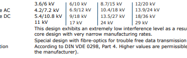
PROTOLON(SMK)-LWL is a medium voltage reeling cable with integrated optical fibres, designed in accordance with German industrial standards DIN VDE 0250-813, with additional compliance to various international specifications. It carries GOST-R certification, making it suitable for use across multiple regions and industries. The cable is available in several voltage classes – 3.6/6kV, 6/10kV, 8.7/15kV, and 12/20kV – and can be engineered for higher ratings up to 18/30kV to suit the requirements of South African port applications. This versatility ensures that there is a suitable variant for almost any STS crane installation.
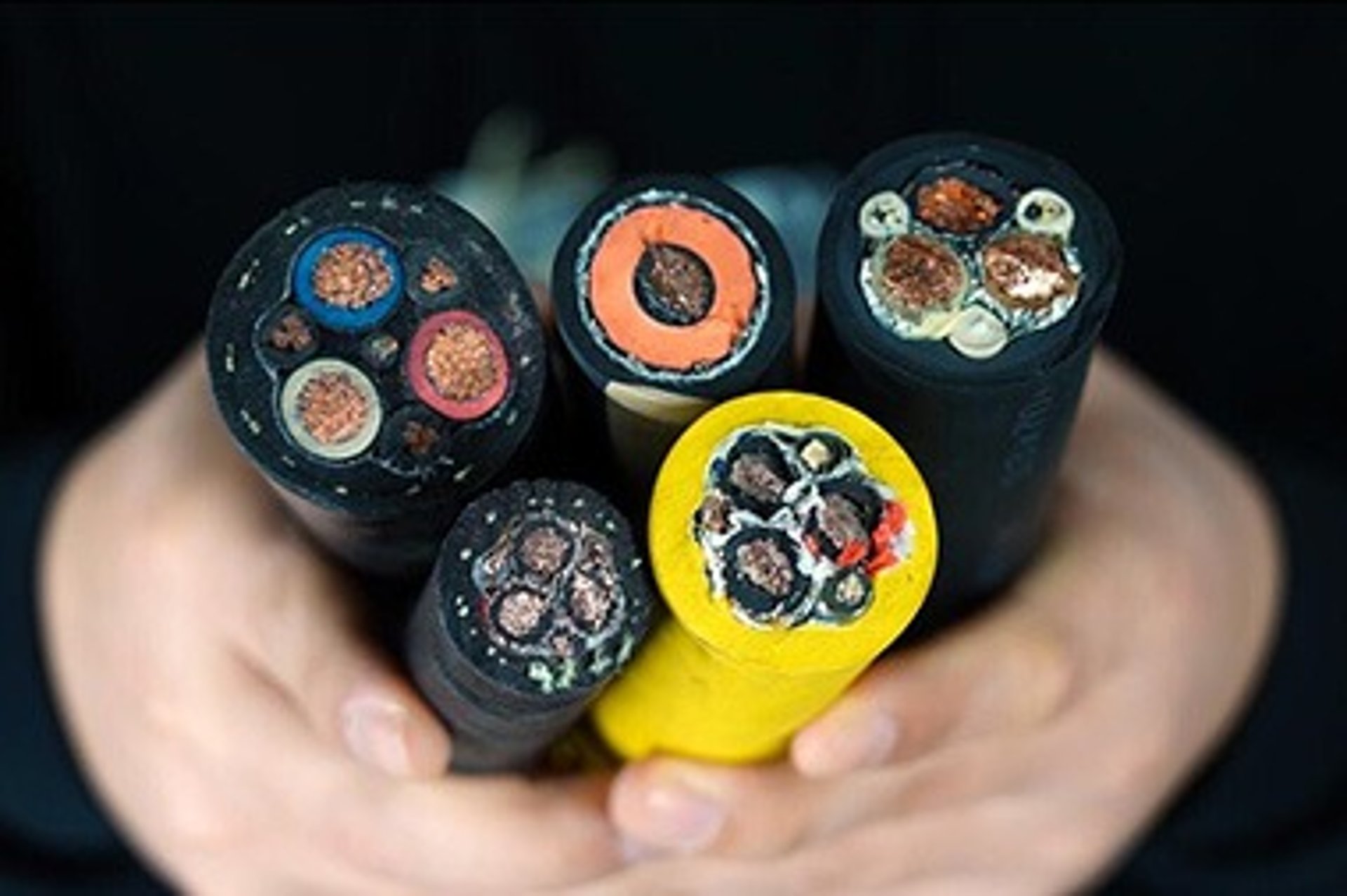
Cable Construction and Materials
The design of PROTOLON(SMK)-LWL reflects decades of engineering experience and material science innovation. Every component has been selected and configured to work together, providing superior performance in dynamic operating environments.
Electrical Components
The power carrying elements are constructed using tinned electrolytic copper conductors. These are made from very fine strands twisted together in accordance with Class FS standards (DIN VDE 0295). This construction offers excellent flexibility, allowing the cable to bend repeatedly without causing conductor fatigue or breakage. The tin plating provides enhanced corrosion resistance, particularly important in coastal environments, and improves electrical connection reliability at termination points.
Insulation is formed from PROTOLON HS, a proprietary high-grade compound based on ethylene propylene rubber (EPR), meeting or exceeding the requirements of class 3GI3 according to DIN VDE 0207 Part 20. This material offers exceptional electrical insulation properties, high thermal stability, and excellent resistance to mechanical stress. It maintains its performance characteristics even after years of continuous movement and exposure to environmental factors.
A sophisticated field control system ensures that electrical stress is distributed evenly within the cable, preventing localised high-field regions that could lead to insulation breakdown. This system consists of two semiconductive layers: an inner layer made from EPR and an outer layer from modified nitrile butadiene rubber (NBR). A key feature of the outer layer is its "Easy Strip" property, which allows it to be removed cleanly and quickly during installation without specialised heating equipment, significantly reducing termination time and effort.
Earth conductors are integrated into the design, split into two equal sections and positioned in the interstices between the main power cores. This arrangement maintains balanced electrical performance while ensuring effective grounding and fault protection.
Fibre Optic Elements
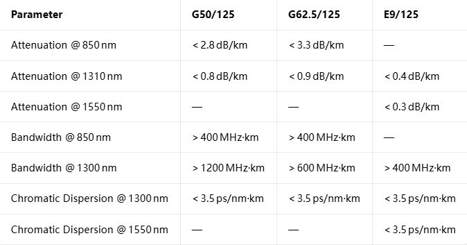
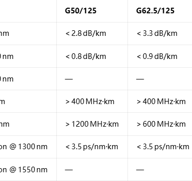
The optical communication elements are carefully engineered to protect the delicate glass fibres while maintaining optimal signal transmission characteristics. Three different fibre types are available to suit different application requirements: G50/125µm, G62.5/125µm, and E9/125µm. All fibres have a cladding diameter of 125µm and a protective coating of 250µm, with core diameters varying according to type.
Fibres are grouped into loose tubes made from ethylene tetrafluoroethylene (ETFE), a high-performance polymer chosen for its exceptional mechanical strength, chemical resistance, and wide operating temperature range. Each tube is filled with a specialised gel compound that provides water blocking protection, cushions the fibres against vibration and shock, and ensures that fibres remain free to move within the tube. This freedom of movement is critical, as it means that when the cable is bent or stretched, mechanical forces are absorbed by the tube structure rather than being transferred directly to the fibres.
Available fibre configurations range from 6 to 24 fibres, arranged in six tubes with between one and four fibres per tube. A unique colour coding system is applied to individual fibres to simplify identification during installation and maintenance. The tubes themselves are laid helically around a central strength member and positioned in the low-stress zones within the cable cross-section, further protecting them from mechanical loads.
Sheath System – PROTOFIRM Sandwich Design
The outer protection system, known as the PROTOFIRM Sandwich, represents one of the most innovative aspects of the cable design. It consists of multiple layers working together to provide exceptional protection and performance.
The inner sheath is a double-layer construction using EPR-based compounds of at least class 5GM3 quality. It serves multiple purposes: providing mechanical separation between electrical and optical components, acting as a water barrier to prevent moisture ingress, and creating a stable foundation for the overall structure. It is coloured red for easy identification and quality control.
Sandwiched between the inner and outer sheaths is a specially engineered anti-torsion layer. This consists of high-strength polyester threads braided in a precise pattern and bonded into place during the manufacturing process. This layer significantly increases the cable's resistance to twisting and improves its tensile strength, ensuring that even under high mechanical loads, the internal structure remains stable and protected.
The outer sheath forms the first line of defence against the external environment. It is manufactured from high-grade rubber compounds based on polychloroprene (PCP), meeting or exceeding class 5GM5 standards. This material offers outstanding resistance to abrasion, tearing, oil, ozone, and UV radiation. It maintains its flexibility across a wide temperature range and is specifically formulated to withstand the harsh conditions found in South African port environments. The bright red colour provides high visibility, making the cable easier to inspect and monitor during operation.
Performance Characteristics
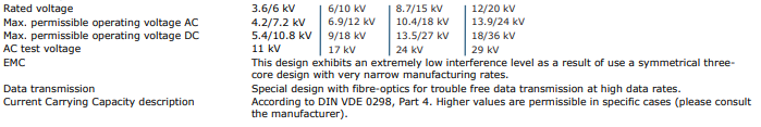
Electrical Performance
Thermal Performance
Temperature resistance is critical in South Africa’s variable climate. PROTOLON(SMK)-LWL is designed to operate continuously with a maximum conductor temperature of 90 °C. Under short‑circuit conditions, it can withstand temperatures up to 250 °C for brief periods without permanent damage.
The ambient operating range is equally impressive. For fixed installations, the cable performs reliably from −50 °C to +80 °C. Even when subjected to continuous movement and flexing, the operating window remains broad, from −35 °C up to +80 °C. This flexibility ensures stable performance whether the cable is exposed to freezing winter nights in Cape Town or intense summer heat in Durban.
Mechanical Performance
Mechanical robustness is where this cable truly excels. It has been engineered from the ground up for dynamic applications. The maximum permitted tensile load on the conductors is 20 N/mm², rising to 30 N/mm² during acceleration phases, well above typical operating loads. It withstands torsional stress of ±25° per metre without degradation, a key specification for equipment that twists and turns constantly.
Bending characteristics are equally impressive. The minimum bending radius follows the requirements of DIN VDE 0298 Part 3, and for S‑shaped directional changes, the recommended minimum distance is 20 times the overall cable diameter. This ensures safe routing even in confined spaces or where complex movement patterns are required.
Speed of operation is practically unlimited for standard gantry reeling applications. For travel speeds above 240 m/min, customised designs are available from the manufacturer to suit specific project needs. Every cable undergoes rigorous qualification testing, including repeated reverse bending cycles, torsion testing, and accelerated ageing trials to verify long‑term reliability.
Environmental Performance
PROTOLON(SMK)-LWL has been formulated to thrive in challenging industrial and coastal environments. Oil resistance meets the strict requirements of DIN EN 60811‑404 and DIN VDE 0473‑811‑404, making it resilient against accidental contact with hydraulic fluids or lubricants. Water resistance complies with HD 2216 standards, ensuring reliable operation even in wet conditions or high humidity.
Weather resistance is a standout feature. The materials and construction are designed for unrestricted indoor and outdoor use, offering high resistance to ozone degradation, UV radiation, and moisture ingress. These qualities make it particularly well suited to South African ports, where salt‑laden air and intense sunlight are constant environmental factors.
In‑Depth Analysis: Key Technical Features and Engineering Principles
Optical Fibre Selection: Multimode vs Singlemode – G50/125, G62.5/125, E9/125
One of the most important choices when specifying PROTOLON(SMK)-LWL is selecting the right type of optical fibre. Three distinct variants are available, each with characteristics that suit different operational needs. Understanding the differences helps to optimise performance and cost‑effectiveness for each installation.
Structural Differences
The G62.5/125 fibre has a core diameter of 62.5 µm and a cladding diameter of 125 µm, with a numerical aperture of 0.275 ± 0.02. The larger core makes alignment and connection easier, and it is more tolerant of small misalignments during termination. These properties make it a practical choice for systems with many connections or where installation conditions are less than ideal.
The G50/125 fibre features a smaller core of 50 µm and the same 125 µm cladding, with a numerical aperture of 0.2 ± 0.02. The reduced core size lowers modal dispersion – the spreading of light pulses as they travel along the fibre – which improves bandwidth and transmission distance. It offers a very good balance between ease of use and performance.
The E9/125 is a single‑mode fibre with a tiny core of just 9 µm. It has a numerical aperture of 0.14 ± 0.02 and guides only a single light path. This design virtually eliminates modal dispersion, enabling the highest bandwidth and longest transmission distances. However, it requires more precise alignment and more specialised termination equipment.
Transmission Performance Comparison
The table below summarises key optical performance parameters for each fibre type:
Attenuation represents signal loss over distance; lower values mean clearer signals over longer ranges. Bandwidth determines how much data can be transmitted at once – higher values support faster communication and more simultaneous services. Chromatic dispersion describes how different wavelengths travel at slightly different speeds; lower values maintain signal shape over distance.
Application Guidance for STS Crane Systems
For South African terminals, the choice of fibre type depends largely on the distance between the shore station and the crane, as well as the volume and speed of data to be transmitted.
G62.5/125 is ideal for shorter runs up to roughly 500 metres. It works well for basic control signals, sensor data, and lower‑resolution video feeds. It is forgiving during installation and is generally the most cost‑effective option for simpler systems.
G50/125 is the recommended choice for most modern automated terminals. It performs well over distances up to about 2 km, supports gigabit‑class speeds, and handles multiple video streams and high‑speed industrial Ethernet protocols easily. It strikes an excellent balance between performance and practicality.
E9/125 should be selected for longer distances or where very high‑bandwidth applications are planned. It supports transmission distances of 10 km or more and provides virtually unlimited bandwidth. It is the best choice for future‑proofing an installation or where the cable will form part of a larger terminal‑wide communications network.
Fibre Performance Optimisation: Attenuation, Bandwidth, and Wavelength Considerations
Understanding how optical signals behave helps explain why PROTOLON(SMK)-LWL performs so reliably. Attenuation is caused by light scattering, absorption by impurities, and bending losses. In well‑designed cables like this one, these factors are carefully controlled to keep signal loss to a minimum.
Bandwidth is limited primarily by dispersion – the tendency of light pulses to spread out as they travel. Multimode fibres are affected by modal dispersion, which is minimised by graded‑index profiles that slow down faster light paths. Singlemode fibres avoid modal dispersion entirely, making them the ultimate choice for high‑capacity links.
Three wavelength windows are widely used in industrial communications, and PROTOLON fibres are optimised for all of them:
850 nm: Used primarily with multimode fibres; cost‑effective for short‑distance applications.
1310 nm: Low attenuation and low dispersion; ideal for medium‑range systems and widely supported by industrial hardware.
1550 nm: The lowest attenuation window; perfect for long‑distance and high‑capacity transmission, particularly with single‑mode fibres.
By selecting the right wavelength and fibre combination, operators can ensure reliable, high‑quality data transmission tailored exactly to their needs.
Fibre Protection: Loose Tube Technology in Dynamic Environments
One of the biggest challenges in designing cables for reeling applications is protecting fragile glass fibres from mechanical stress. PROTOLON(SMK)-LWL solves this through the use of loose tube technology, an engineering principle specifically developed for dynamic environments.
In this design, fibres are housed within tubes made from ETFE – a tough, chemically inert fluoropolymer. The internal diameter of each tube is significantly larger than the outer diameter of the fibre bundle inside, creating physical space. When the cable bends, stretches, or twists, the fibres are free to move slightly within the tube, so that mechanical forces are absorbed by the tube structure rather than being transferred directly to the fibres.
The tubes are filled with a specially formulated thixotropic gel compound. This performs several vital functions: it blocks the movement of water along the cable, it cushions the fibres against vibration and shock, and it holds the fibres gently in place to prevent movement during normal operation.
The tubes themselves are arranged in a helical pattern around a central strength member. This spiral configuration means that as the cable bends, the path length change is distributed evenly across the cross‑section, minimising strain on any individual element. By placing the fibre units in the low‑stress zones between the main power cores, the design further isolates them from mechanical and thermal influences.
Electromagnetic Interference Immunity: Physics of Optical Communication in High‑Voltage Environments
The integration of power and communication in a single cable might seem risky from an interference perspective, but in practice it works extremely well – and for fundamental physical reasons.
Electromagnetic interference occurs when changing electrical currents create magnetic fields, which in turn induce unwanted voltages in nearby conductors. This is the problem that plagues traditional systems where copper control cables run alongside power cables. Optical fibres, however, carry information as pulses of light rather than electrical currents. Glass is an electrical insulator and does not interact with magnetic or electric fields. Consequently, signals travelling along optical fibres remain completely unaffected by the high‑voltage power transmission occurring just millimetres away.
This immunity works in both directions: the optical system does not generate any electrical noise, and the power system cannot corrupt the data stream. It means the cable can be designed with very close spacing between power cores and optical elements without compromising performance, enabling the compact integrated design.
Symmetrical construction also helps to reduce external electromagnetic emissions. The three power cores carry currents that are ideally balanced and 120 degrees out of phase. This arrangement causes their magnetic fields to largely cancel each other out, further minimising the electromagnetic footprint of the system.
Fibre Count Options: 6/12/18/24 Fibres – System Architecture and Flexibility
PROTOLON(SMK)-LWL offers a choice of fibre counts, allowing operators to tailor the system precisely to their requirements. Each configuration supports different system architectures and growth paths.
6‑fibre configuration is the entry‑level option, ideal for basic automation systems. A typical deployment might use two fibres for primary control, two for video transmission, and two kept as spares or for redundant links. It is cost‑effective and sufficient for terminals with simpler automation levels.
12‑fibre configuration is the most popular choice and the standard recommendation for South African ports. It provides enough capacity to support multiple independent services simultaneously. A common arrangement allocates two fibres for safety‑critical control, two for operational data, four for video streams, and four for future expansion or redundancy. This configuration supports ring, star, or linear network topologies and makes it easy to introduce new systems without changing the cabling infrastructure.
18 and 24‑fibre configurations are designed for large‑scale, highly automated terminals or where the cable forms part of a wider communications backbone. With this many channels, it becomes possible to separate different systems completely – for example, having dedicated fibres for machinery control, terminal management systems, security, and maintenance networks. It also supports multi‑vendor environments and allows operators to implement diverse redundancy strategies for maximum reliability.
Whichever configuration is chosen, the colour‑coding system ensures that every fibre can be identified quickly and accurately during installation, testing, or maintenance.
Matching Cable Capabilities to Automated Crane Control Requirements
Modern STS cranes place very specific demands on communication systems, and PROTOLON(SMK)-LWL is engineered to meet them exactly.
Real‑time control loops require the lowest possible latency. Signals must travel from sensors to controllers and back to actuators in milliseconds or less. Optical transmission offers propagation speeds close to the speed of light, so the physical travel time is negligible – typically less than one microsecond for a 200 metre run. This speed allows even the most demanding closed‑loop control systems to perform optimally.
Condition monitoring systems generate large volumes of data at high sample rates. Fibre optics easily handle the bandwidth requirements, enabling comprehensive monitoring of temperatures, vibrations, pressures, and electrical parameters across the crane structure. This data supports predictive maintenance programmes that help reduce downtime and extend equipment life.
Video surveillance is increasingly important in automated terminals. Multiple high‑definition cameras may be installed, each requiring data rates of tens or hundreds of megabits per second. PROTOLON fibres support these high‑bandwidth streams with ease, delivering clear, stable images essential for both automatic vision systems and remote human operators.
Integration with Terminal Operating Systems (TOS) is another key function. The communication network connects the crane to the central management system, allowing operational data to be shared across the facility. The high reliability and bandwidth of the fibre system ensure smooth data flow, even during peak operational periods.
Installation and Termination: Factory Assembly vs Field Implementation
Successful deployment depends not only on cable quality but also on how it is installed and connected. PROTOLON(SMK)-LWL offers two approaches to termination, each with its own advantages.
Factory Assembly
Factory termination is the recommended option where possible. Here, the cable is cut to length and fitted with high‑quality connectors in controlled manufacturing facilities before delivery. This approach offers several benefits:
Termination is performed by trained specialists using precision equipment, ensuring low insertion loss – typically less than 0.3 dB per connection.
Every assembly is fully tested before dispatch, so performance is guaranteed from day one.
Installation time on site is reduced to simple mechanical fixing and plug‑and‑play connection.
It minimises the requirement for specialised skills and expensive test equipment at the terminal.
Factory assemblies can be supplied with a wide range of connector types to suit existing infrastructure, including LC, SC, ST, and FC connectors, as well as specialised industrial connectors designed for harsh environments.
Field Installation
Where factory‑terminated lengths are not practical or where modifications are required on site, field termination is also possible. Two main techniques are used:
Fusion splicing: The fibres are precisely cleaved, aligned, and fused together using an electric arc. This creates a permanent joint with very low loss – typically below 0.05 dB – and excellent long‑term stability. It requires specialised equipment and trained operators but produces the best possible results.
Mechanical connectors: Pre‑polished ferrules and alignment sleeves are used to join fibres without heat or fusion equipment. They are faster to install and require less training, though losses are generally higher – usually between 0.1 and 0.3 dB. They are ideal for quick repairs or temporary connections.
Regardless of the method chosen, certain principles apply. Minimum bend radii must be observed to prevent signal loss or fibre breakage. Cleanliness is critical – even microscopic dust particles on fibre ends can significantly degrade performance. Every joint should be tested with an optical power meter or OTDR (Optical Time‑Domain Reflectometer) to verify quality before commissioning.
Connection enclosures should be chosen carefully, with ingress protection ratings of at least IP67 to withstand the environmental conditions found in South African ports. Proper sealing and strain relief are essential to maintain performance over time.
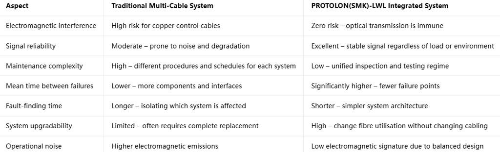
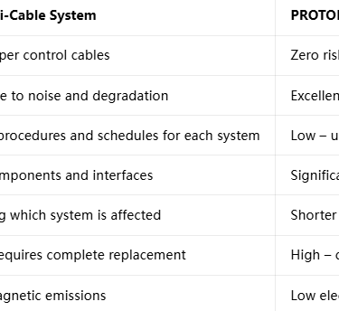
Side‑by‑Side Comparison: Integrated vs Independent Cabling Systems
To fully understand the value of PROTOLON(SMK)-LWL, it is helpful to compare it directly with the traditional approach of using separate power and data cables. The following tables summarise key differences across three main categories: infrastructure, performance, and economics.
Operational Performance
Total Cost of Ownership – Full Lifecycle Analysis
When assessing infrastructure investments, it is important to look beyond initial purchase price and consider costs over the entire service life, typically 10 – 15 years for port cabling systems.
Capital expenditure for a traditional installation includes not only the cables themselves but also multiple reel drives, separate guide systems, different types of connectors, junction boxes, and specialised termination kits. For an average STS crane installation, this can amount to a substantial investment. With PROTOLON(SMK)-LWL, the single‑cable design reduces material costs and simplifies hardware requirements, resulting in typical capital savings of between 25 % and 35 % compared to the traditional approach.
Operational expenditure savings are even more significant. Maintenance labour hours are reduced by approximately 40 – 50 % because there is only one system to inspect, test, and maintain. Spare parts inventories can be streamlined, and training requirements are simplified. Perhaps most importantly, the improved reliability of the integrated system reduces unplanned downtime. Based on data from installations around the world, operators can expect annual savings of between USD 15,000 and USD 30,000 per crane through reduced maintenance and increased operational availability.
Lifecycle extension is another financial benefit. The high‑grade materials and robust construction of PROTOLON(SMK)-LWL give it an expected service life of 12 – 15 years, compared to 8 – 10 years typical for traditional systems. This longer life delays the need for costly replacement and improves the return on investment. When combined with the other savings, the integrated system often proves to be significantly cheaper over its lifetime, even if the initial purchase price per metre is slightly higher.
Field Performance and Deployment Strategy for South African Automated Terminals
Real‑World Operational Performance Data
Since its introduction, PROTOLON(SMK)-LWL has been deployed in ports across the world, including several facilities operating under conditions similar to those found in South Africa. The accumulated operational data confirms the performance claims and highlights the benefits in real service environments.
Mechanical reliability has been impressive. In installations where the cable has completed more than two million bending cycles, testing has shown no measurable increase in fibre attenuation or electrical resistance. The cable maintains its structural integrity even after years of continuous movement. Torsion performance has also exceeded expectations, with installations showing stable operation after more than 100,000 twisting cycles at ±20° per metre – well within the design specifications. Tensile strength retention remains above 90 % even after five years of service, demonstrating the effectiveness of the PROTOFIRM sandwich construction.
Environmental resilience has been particularly notable in coastal applications. Salt spray testing according to IEC 60068‑2‑11 has shown no degradation after 1,000 hours of exposure, confirming the suitability for South Africa’s marine environments. UV stability is equally impressive, with the outer sheath retaining more than 80 % of its mechanical properties following 5,000 hours of accelerated ageing testing. Temperature cycling from –30 °C to +75 °C has produced no measurable change in electrical or optical performance, validating the material selection for local climate conditions.
Communication stability is consistently high. Field measurements show bit error rates regularly below 10⁻¹², which is well within industrial standards and more than sufficient for the most demanding control applications. Latency variation is typically less than one microsecond, making the system ideal for closed‑loop control where timing precision is critical. Overall signal availability in operational installations has been recorded at better than 99.999 %, meaning less than five minutes of communication downtime per year – a level that is practically impossible to achieve with traditional systems.
Best Practices for System Design and Deployment
To achieve the best possible results with PROTOLON(SMK)-LWL, certain principles should be followed during the design and installation phases. These guidelines have been developed through years of experience and are particularly relevant for South African port conditions.
Cable Sizing and Specification Selection
Choosing the correct cable variant is the first step in a successful installation. For most STS crane applications operating at 18 – 30 kV, the 8.7/15 kV or 12/20 kV rated cables are recommended. While they operate below their maximum voltage capacity, this practice provides a safety margin that improves reliability and extends service life.
Conductor size should be selected based on maximum load requirements and cable length. For typical STS cranes with peak loads of 18 – 20 MW, the 3 × 185 mm² configuration provides sufficient capacity with acceptable voltage drop. Where future expansion is anticipated or where cable runs are longer than 150 metres, upgrading to 3 × 240 mm² conductors is advisable.
Fibre type selection should be based on distance and bandwidth requirements. For installations shorter than 500 m, G62.5/125 fibres provide a cost‑effective solution. For most modern terminals with runs between 500 m and 2 km, G50/125 fibres offer the best balance of performance and economy. For longer distances or where high‑bandwidth applications are planned, E9/125 single‑mode fibres are the preferred choice.
Reel and Guiding System Design
The performance of any reeling cable depends heavily on the equipment it runs on. Reel diameter should be at least 20 times the cable’s outer diameter to ensure bending stresses remain within safe limits. Wherever possible, larger diameters should be used to further reduce fatigue. For multi‑layer winding systems, the reel should be designed with precise tension control, maintaining consistent tension throughout the winding process. This prevents excessive compression of the lower layers, which can damage the cable over time.
Guide rollers play a crucial role in protecting the cable. They should be made from low‑friction, wear‑resistant materials such as polyurethane or nylon, with diameters that match or exceed the minimum bending radius requirements. Roller alignment must be precise to prevent side‑loading, which can cause twisting or abrasion. Where cables change direction, gradual bends are always preferable to sharp turns.
Connection and Termination Planning
Termination points are among the most vulnerable parts of any cable system, and careful planning pays dividends in reliability. Wherever possible, connections should be located in fixed positions such as machinery rooms or gantry bases rather than on moving parts. This reduces mechanical stress on connectors and simplifies maintenance.
Enclosures for connection points should have an ingress protection rating of at least IP67 to withstand dust, water, and salt spray. They should be constructed from corrosion‑resistant materials such as stainless steel or glass‑reinforced plastic. Proper cable entry sealing is essential to maintain environmental protection, and glands should be sized correctly for the cable diameter.
Grounding and bonding deserve special attention. Even though the optical elements are immune to interference, proper grounding of the cable sheath and metallic components is essential for electrical safety and system performance. Grounding arrangements should follow international standards and local electrical regulations, ensuring equipotential bonding across all moving parts.
Integration with Terminal Automation Systems
Modern port operations rely heavily on sophisticated software systems, and the cabling infrastructure forms the backbone of these networks. PROTOLON(SMK)-LWL is designed to be compatible with all major industrial communication protocols, including PROFINET, EtherNet/IP, Modbus TCP, and Ethernet POWERLINK. This compatibility simplifies integration with existing systems and provides flexibility for future upgrades.
Redundancy design is an important consideration for mission‑critical systems. With multiple fibres available, operators can implement redundant communication paths within the same cable. This approach provides protection against fibre damage or equipment failure without requiring duplicate cabling infrastructure. For the highest levels of reliability, parallel cables can be installed in physically separate routes, creating a completely redundant system.
Network management should be considered from the outset. The optical fibres support standard monitoring protocols, allowing operators to continuously check signal quality, measure attenuation, and detect potential issues before they cause failures. Integration with SNMP‑based monitoring systems enables centralised supervision of the entire communications infrastructure.
Frequently Asked Questions
Product and Specification Questions
Q: What voltage classes are available for PROTOLON(SMK)-LWL cables?
A: Standard ratings include 3.6/6 kV, 6/10 kV, 8.7/15 kV and 12/20 kV. Customised designs up to 18/30 kV can be engineered specifically for high‑power STS crane applications, making them suitable for all common voltage levels found in South African ports.
Q: Which fibre type should I choose for my specific application?
A:
G62.5/125 µm: Best for short‑distance applications below 500 m, where cost‑effectiveness and ease of termination are priorities.
G50/125 µm: The recommended choice for most modern automated terminals, offering excellent performance over distances up to 2 km.
E9/125 µm: Ideal for long‑distance links over 2 km, ultra‑high‑bandwidth requirements, or where future expansion is planned.
Q: Can the cable be used outdoors and in coastal environments?
A: Yes. The cable is fully weather‑resistant, UV‑stabilised, and formulated to resist the corrosive effects of salt‑laden air. It meets all relevant standards for outdoor and marine applications and performs reliably in the environmental conditions typical of South African ports.
Q: Can I get custom fibre configurations?
A: Absolutely. While standard options are 6, 12, 18 and 24 fibres, custom configurations with different numbers or mixes of fibre types are available on request. This flexibility allows operators to design systems that exactly match their specific requirements.
Installation and Operation Questions
Q: Is special training required for fibre termination?
A: Field termination requires standard fibre optic skills and equipment. For highest performance and reliability, however, factory‑terminated assemblies are strongly recommended. These are supplied ready‑for‑use and require no special skills to install, making them ideal for terminal environments.
Q: What is the minimum bending radius?
A: During installation, the minimum bending radius is 15 times the outer diameter of the cable. During normal operation, this reduces to 10 times the outer diameter for static applications and 20 times the outer diameter during dynamic reeling. These values are well within the capabilities of standard reel and guide systems.
Q: Can PROTOLON(SMK)-LWL replace existing multi‑cable systems?
A: In most cases, yes. Because it combines multiple functions into a single cable, it can directly replace separate power, control, and communication cables. In many retrofits, the existing reel mechanisms can be adapted rather than replaced, significantly reducing upgrade costs and installation time.
Q: What maintenance is required?
A: Maintenance requirements are straightforward and less demanding than for multi‑cable systems. Visual inspections should be carried out every 3 – 6 months to check for physical damage or wear. Electrical testing should be performed annually, and optical performance testing every 2 – 3 years. This simple regime ensures reliable performance throughout the cable’s service life.
Performance and Reliability Questions
Q: Is there any risk of electrical interference affecting the optical signals?
A: No. Optical fibres transmit data as pulses of light rather than electrical signals, making them completely immune to electromagnetic interference. Even when running alongside high‑voltage power conductors, the communication system remains unaffected. This fundamental advantage is one of the key reasons why integrated systems perform so well in industrial environments.
Q: What is the expected service life?
A: Under normal operating conditions, PROTOLON(SMK)-LWL has a design life of more than 10 years. In practice, many installations operate reliably for 12 – 15 years or longer when properly maintained. This represents a significant improvement over traditional systems, which typically require replacement every 8 – 10 years.
Conclusion
Summary of Key Advantages
The move towards automation in South Africa’s container terminals brings significant opportunities to improve productivity, safety, and efficiency. However, it also places increasing demands on the infrastructure that supports these advanced systems. PROTOLON(SMK)-LWL represents a major step forward in cable technology, addressing many of the limitations that have constrained port operators for decades.
By integrating medium‑voltage power distribution and high‑speed data communication into a single cable assembly, this innovative solution reduces complexity, lowers costs, and improves reliability. The carefully engineered construction uses advanced materials science and proven optical technology to create a product that performs exceptionally well even under the most challenging conditions.
The benefits are felt at every stage of the system lifecycle. During design and installation, the simplified architecture reduces engineering effort, shortens installation times, and lowers capital costs. Throughout the operational life, the integrated design reduces maintenance requirements, improves system availability, and provides the flexibility to adapt to changing needs. Even at the end of life, the unified system is easier to replace and recycle.
Strategic Value for South African Port Operators
For South Africa’s port operators, the adoption of technologies like PROTOLON(SMK)-LWL offers more than just operational improvements. It represents a strategic investment that helps position local ports as modern, efficient, and competitive players in the global logistics network. By reducing operating costs and improving reliability, it helps make South African ports more attractive to shipping lines and cargo owners.
The improved performance of automated systems supported by this technology enables higher throughput rates, faster vessel turnaround times, and more consistent service quality. These improvements directly contribute to the economic performance of the ports and the regions they serve. Additionally, the enhanced safety and environmental performance align with international best practices and regulatory requirements.
Final Recommendations
Based on the detailed analysis and operational experience, several recommendations emerge for South African port operators and engineering teams:
For new terminal projects or major equipment upgrades, PROTOLON(SMK)-LWL should be specified as the preferred cabling solution. The initial investment is offset by significant savings over the system life, and the performance benefits support the long‑term goals of automation and digitalisation.
For existing facilities, the technology offers an attractive upgrade path. Retrofitting existing STS cranes with integrated cabling systems can deliver immediate improvements in reliability and performance, often without the need for major mechanical modifications.
Working with experienced suppliers is key to realising the full benefits of this technology. Professional engineering support ensures that the right specifications are selected, installation is carried out correctly, and ongoing maintenance is properly managed.
If you are planning a new automated container terminal, upgrading existing STS crane systems, or seeking expert advice on integrated power and communication cabling solutions, contact the Feichun Special Cable technical team today.
📧 Email: Li.wang@feichuncables.com
Our engineering specialists are available to provide:
Custom cable specification and system design tailored to your exact requirements
Installation guidance and training support for your technical teams
Lifecycle cost analysis and return on investment calculations
Product samples and full technical documentation
Feichun Special Cable combines global technology leadership with local support, ensuring that you get the right solution for South African conditions. Reach out today to discuss how PROTOLON(SMK)-LWL can help you build more reliable, efficient, and future‑ready port operations.
Email Address: Li.wang@feichuncables.com
© 2025. All rights reserved.


One-click to Quickly Contact
Products
Contact
Company
Location:
Building A Private Science and Technology Park, Hefei Economic and Technological Development Zone, Anhui Province, China
Heat Resistant Cable
WhatsApp: +86 17333223430
Social Media: