RG7H1R
Application
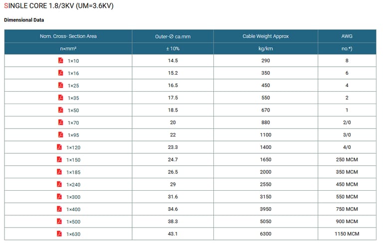
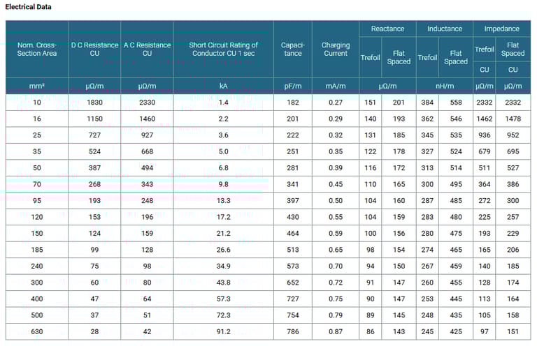
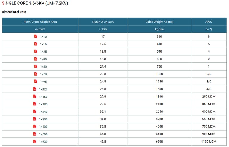
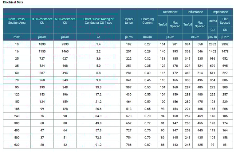
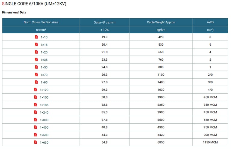
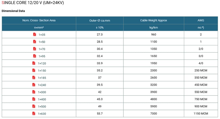
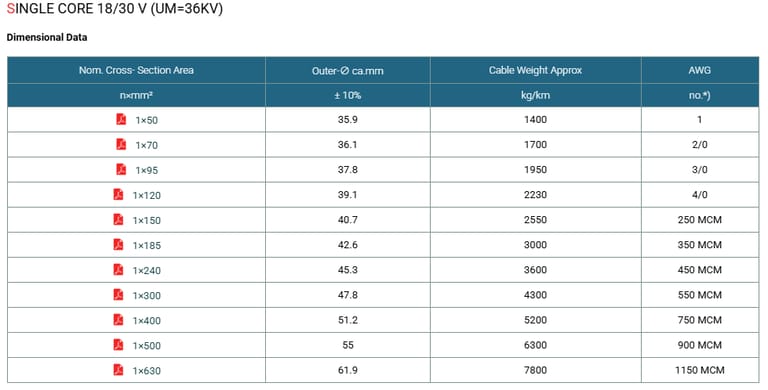
The single core cables are designed for distribution of electrical power with nominal voltage Uo/U ranging from 1.8/3KV to 18/30KV and frequency 50Hz. They are suitable for installation mostly in power supply stations, indoors and in cable ducts, outdoors, underground and in water as well as for installation on cable trays for industries, switchboards and power stations.
Standards
IEC 60502 / CEI 20-13
Flame Retardant:
DIN VDE 0482 part 265-2-1
EN 50265-2-1
EN 60332-1-2
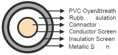
Construction
Conductor : Plain annealed copper with IEC 60228 class 2.
Conductor Screen : The conductor screen consists of an extruded layer of non metallic, semi-conducting compound firmly bonded to the insulation to exclude all air voids.
Insulation : Rubber, type G7 .
Insulaton Screen : The insulation screen consists of an extruded layer of non metallic, semiconducting compound extruded over the insulation. The extruded semi-conducting layer shall consist of bonded or cold strippable semi-conducting compound capable of removal for jointing or terminating. As an option, a semi-conducting tape may be applied over the extruded semi-conducting layer as a bedding for the metallic layer. The minimum thickness is 0.3 mm and the maximum resistivity is 500 Ohm-m at 90°C. The screen is tightly fitted to the insulation to exclude all air voids and can be easily hand stripped on site.
Over Sheath : Red(RAL 3000), PVC, type RZ, other dimensions and colours available on request.
Table 2a. Total Cross Section and Max. DC Resistance of Copper Wire Screen
Nom. Cross Section Area of Conductor | Total Cross Section | Max. DC Resistance at 20 ℃ | ||||
|---|---|---|---|---|---|---|
3.6/6KV (Um=7.2KV) | 6/10KV (Um=12KV) | 8.7/15KV (Um=17.5KV) | 12/20KV (Um=24KV) | 18/30KV (Um=36KV) | ||
mm² | mm | mm | mm | mm | mm | Ω |
10 | 10 | 10 | 10 | 10 | 10 | 1.075 |
16 | 16 | 16 | 16 | 16 | 16 | 1.075 |
25 | 16 | 16 | 16 | 16 | 16 | 1.075 |
35 | 16 | 16 | 16 | 16 | 16 | 1.075 |
50 | 16 | 16 | 16 | 16 | 16 | 1.075 |
70 | 16 | 16 | 16 | 16 | 16 | 1.075 |
95 | 16 | 16 | 16 | 16 | 16 | 1.075 |
120 | 16 | 16 | 16 | 16 | 16 | 1.075 |
150 | 25 | 25 | 25 | 25 | 25 | 0.688 |
185 | 25 | 25 | 25 | 25 | 25 | 0.688 |
240 | 25 | 25 | 25 | 25 | 25 | 0.688 |
300 | 25 | 25 | 25 | 25 | 25 | 0.688 |
400 | 35 | 35 | 35 | 35 | 35 | 0.491 |
500 | 35 | 35 | 35 | 35 | 35 | 0.491 |
630 | 35 | 35 | 35 | 35 | 35 | 0.491 |
800 | 50 | 50 | 50 | 50 | 50 | 0.344 |
1000 | 50 | 50 | 50 | 50 | 50 | 0.344 |
Table 2a. Total Cross Section and Max. DC Resistance of Copper Tape Screen (0.1mm)
Nom. Cross Section Area of Conductor | Total Cross Section & Max. DC Resistance | |||||||||
|---|---|---|---|---|---|---|---|---|---|---|
3.6/6KV (Um=7.2KV) | 6/10KV (Um=12KV) | 8.7/15KV (Um=17.5KV) | 12/20KV (Um=24KV) | 18/30KV (Um=36KV) | ||||||
Total Cross Section | Max. DC Resistance at 20 ℃ | Total Cross Section | Max. DC Resistance at 20 ℃ | Total Cross Section | Max. DC Resistance at 20 ℃ | Total Cross Section | Max. DC Resistance at 20 ℃ | Total Cross Section | Max. DC Resistance at 20 ℃ | |
mm² | mm |
| mm |
| mm |
| mm |
| mm |
|
10 | 4.7 | 3.646 | - | - | - | - | - | - | - | - |
16 | 5.1 | 3.342 | 5.9 | 2.925 | - | - | - | - | - | - |
25 | 5.7 | 3.025 | 6.4 | 2.679 | 7.3 | 2.350 | 8.1 | 2.114 | - | - |
35 | 6.2 | 2.796 | 6.9 | 2.498 | 7.8 | 2.210 | 8.6 | 2.000 | - | - |
50 | 6.7 | 2.568 | 7.4 | 2.314 | 8.3 | 2.064 | 9.1 | 1.880 | 11.2 | 0.579 |
70 | 7.4 | 2.314 | 8.2 | 2.106 | 9.1 | 1.897 | 9.9 | 1.740 | 11.9 | 0.543 |
95 | 8.2 | 2.095 | 8.9 | 2.925 | 9.8 | 1.748 | 10.7 | 1.614 | 12.7 | 0.510 |
120 | 9.0 | 1.905 | 9.8 | 2.679 | 10.7 | 1.613 | 11.5 | 1.498 | 13.5 | 0.479 |
150 | 9.7 | 1.781 | 10.4 | 2.498 | 11.3 | 1.523 | 12.1 | 1.420 | 14.2 | 0.458 |
185 | 10.6 | 1.626 | 11.2 | 2.314 | 12.2 | 1.407 | 12.9 | 1.335 | 14.9 | 0.434 |
240 | 11.7 | 1.465 | 12.4 | 2.106 | 2.106 | 1.294 | 14.1 | 1.219 | 16.2 | 0.401 |
300 | 12.9 | 1.334 | 13.4 | 1.923 | 1.923 | 1.204 | 15.1 | 1.139 | 17.1 | 0.378 |
400 | 14.3 | 1.205 | 14.6 | 1.761 | 1.761 | 1.110 | 16.3 | 1.054 | 18.4 | 0.353 |
500 | 15.7 | 1.094 | 16.2 | 1.655 | 1.655 | 1.005 | 17.5 | 0.982 | 20.0 | 0.325 |
630 | 17.3 | 0.992 | 18.9 | 1.540 | 1.540 | 0.918 | 19.5 | 0.880 | 21.6 | 0.300 |
800 | 20.3 | 0.849 | 20.4 | 1.388 | 21.3 | 0.807 | 22.1 | 0.777 | 24.2 | 0.268 |
1000 | 22.3 | 0.771 | 22.4 | 1.285 | 23.3 | 0.738 | 24.1 | 0.713 | 26.2 | 0.248 |
Physical Properties
Temperature Range : -15°C / +90°C
Max Short Circuit Temperature : +250°C
Min Installation Temperature : 0°C
Min Bending Radius : 12 x OD
Max. Tensile Stress : 60 N/mm²
Table 4. Nominal /Operating /Testing Voltages
Rated Voltage Uo/U | Operating Voltage (Um) | Testing Voltage (rms) |
|---|---|---|
1.8/3KV | 3.6KV | 6KV |
3.6/6KV | 7.2KV | 11KV |
6/10KV | 12KV | 17KV |
8.7/15KV | 17.5KV | 24KV |
12/20KV | 24KV | 29KV |
18/30KV | 36KV | 45KV |