Single Core Cables to BS 6622 / BS 7835
Single Core Cables Adhering to British Standards BS 6622 and BS 7835 Stand Out as Robust Solutions for High-voltage Applications
Single Core Cables to BS 6622 / BS 7835
Application
The single core cables are designed for distribution of electrical power with nominal voltage Uo/U ranging from 3.8/6.6KV to 19/33KV and frequency 50Hz. They are suitable for installation mostly in power supply stations, indoors and in cable ducts, outdoors, underground and in water as well as for installation on cable trays for industries, switchboards and power stations.
Standards
BS 6622
BS 7835 (LSZH)
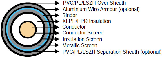
Construction
Conductor : Plain annealed copper or aluminium complying with IEC 60228/BS 6360. Copper conductors shall be stranded (class 2) and aluminium conductors shall be either solid or stranded (class 2).
Conductor Screen : Extruded layer of semi-conducting cross-linkable compound is applied over the conductor and shall cover the surface completely. The minimum thickness is 0.3mm and the maximum resistivity shall not exceed 500 Ohm-m at 90°C.
Insulation : Insulation is of cross-linked polyethylene compound XLPE (GP8) conforming to BS 7655-1.3 or EPR (GP7), conforming to BS 7655-1.2.
Table 1. Insulation Thickness
Nom. Cross Section Area | Insulation Thickness at Nominal Voltage | ||||
|---|---|---|---|---|---|
3.8/6.6KV (Um=7.2KV) | 6.35/11KV (Um=12KV) | 8.7/15KV(Um=17.5KV) | 12.7/22KV(Um=24KV) | 19/33KV(Um=36KV) | |
mm² | mm | mm | mm | mm | mm |
70 – 185 | 2.5 | 3.4 | 4.5 | 5.5 | 8.0 |
240 | 2.6 | 3.4 | 4.5 | 5.5 | 8.0 |
300 | 2.8 | 3.4 | 4.5 | 5.5 | 8.0 |
400 | 3.0 | 3.4 | 4.5 | 5.5 | 8.0 |
Above 500 | 3.2 | 3.4 | 4.5 | 5.5 | 8.0 |
Insulaton Screen : Extruded layer of semi-conducting cross-linkable compound is applied over the insulation. The extruded semi-conducting layer shall consist of bonded or cold strippable semi-conducting compound capable of removal for jointing or terminating. As an option, a semi-conducting tape may be applied over the extruded semi-conducting layer as a bedding for the metallic layer. The minimum thickness is 0.3 mm and the maximum resistivity is 500 Ohm-m at 90°C. The screen is tightly fitted to the insulation to exclude all air voids and can be easily hand stripped on site.
Metallic Layer : The metallic layer shall consist of either copper tapes or a concentric layer of copper wires or a combination of tapes and wires. The metallic layer provides an earth fault current path, capable of withstanding fault current to earth of 1000A for one second at maximum temperature 160°C. Copper wires are applied over the conducting water blocking layer with a minimum diameter of 0.5mm. As an alternative, copper tape(s) with minimum thickness of 0.1mm can be applied with overlap. Total cross section of copper wire screen and copper tape screen layer are shown in Table 2a and 2b.
Table 2a. Total Cross Section and Max. DC Resistance of Copper Wire Screen
Nominal Cross-Section of Cables | Total Cross Section | Max. DC Resistance of Copper Wire Screen at 20℃ | ||||
|---|---|---|---|---|---|---|
3.8/6.6KV (Um=7.2KV) | 6.35/11KV (Um=12KV) | 8.7/15KV (Um=17.5KV) | 12.7/22KV (Um=24KV) | 19/33KV (Um=36KV) | ||
mm² | mm² | Ω | ||||
70 | 16 | 16 | 16 | 16 | 16 | 1.19 |
95 | 16 | 16 | 16 | 16 | 16 | 1.19 |
120 | 16 | 16 | 16 | 16 | 16 | 1.19 |
150 | 25 | 25 | 25 | 25 | 25 | 0.759 |
185 | 25 | 25 | 25 | 25 | 25 | 0.759 |
240 | 25 | 25 | 25 | 25 | 25 | 0.759 |
300 | 25 | 25 | 25 | 25 | 25 | 0.759 |
400 | 35 | 35 | 35 | 35 | 35 | 0.271 |
500 | 35 | 35 | 35 | 35 | 35 | 0.217 |
630 | 35 | 35 | 35 | 35 | 35 | 0.271 |
Table 2b. Total Cross Section and Max. DC Resistance of Copper Tape Screen (0.1mm)
Nominal Cross-Section of Conductor | Total Cross Section & Max DC Resistance | |||||||||
|---|---|---|---|---|---|---|---|---|---|---|
3.8/6.6KV (Um=7.2KV) | 6.35/11KV (Um=12KV) | 8.7/15KV (Um=17.5KV) | 12.7/22KV (Um=24KV) | 19/33KV (Um=36KV) | ||||||
Total Cross Section | Max. DC Resistance at 20℃ | Total Cross Section | Max. DC Resistance at 20℃ | Total Cross Section | Max. DC Resistance at 20℃ | Total Cross Section | Max. DC Resistance at 20℃ | Total Cross Section | Max. DC Resistance at 20℃ | |
mm² | mm² | Ω | mm² | Ω | mm² | Ω | mm² | Ω | mm² | Ω |
70 | 7.4 | 2.314 | 8.2 | 2.106 | 9.1 | 1.897 | 9.9 | 1.740 | 11.9 | 1.442 |
95 | 8.2 | 2.095 | 8.9 | 1.923 | 9.8 | 1.748 | 10.7 | 1.614 | 12.7 | 1.354 |
120 | 9.0 | 1.905 | 9.8 | 1.761 | 10.7 | 1.613 | 11.5 | 1.498 | 13.5 | 1.272 |
150 | 9.7 | 1.781 | 10.4 | 1.655 | 11.3 | 1.523 | 12.1 | 1.420 | 14.2 | 1.215 |
185 | 10.6 | 1.626 | 11.2 | 1.540 | 12.2 | 1.407 | 12.9 | 1.335 | 14.9 | 1.153 |
240 | 11.7 | 1.465 | 12.4 | 1.388 | 13.3 | 1.294 | 14.1 | 1.219 | 16.2 | 1.065 |
300 | 12.9 | 1.334 | 13.4 | 1.285 | 14.3 | 1.204 | 15.1 | 1.139 | 17.1 | 1.003 |
400 | 14.3 | 1.205 | 14.6 | 1.178 | 15.5 | 1.110 | 16.3 | 1.054 | 18.4 | 0.937 |
500 | 15.7 | 1.094 | 16.2 | 1.061 | 17.1 | 1.005 | 17.5 | 0.982 | 20.0 | 0.861 |
630 | 17.3 | 0.992 | 18.9 | 0.912 | 18.7 | 0.918 | 19.5 | 0.880 | 21.6 | 0.797 |
Separation Sheath (for armoured cable) : The separation sheath comprises a layer of extruded PVC, PE or LSZH. The nominal thickness is calculated by 0.02Du + 0.6mm where Du is the fictitious diameter under the sheath in mm. The nominal separation sheath thickness shall not be less than 1.2mm.
Armour (for armoured cable) : The armour consists of round aluminium wire with diameter specified as in Table 3.
Table 3. Armour Wire Diameter
Fictitious Diameter Under the Armour | Armour Wire Diameter | |
|---|---|---|
mm | mm | |
> | < |
|
- | 25 | 1.6 |
25 | 35 | 2.0 |
35 | 60 | 2.5 |
60 | - | 3.15 |
Over Sheath : Overall sheath comprises a layer of extruded either PVC type 9 conforming to BS 7665-4.2 or MDPE type TS2 conforming to BS 7655-10.1. LSZH can be offered as an option. The over sheath is normally black in colour. When a DC voltage test is to be performed on the over sheath, a semi-conducting layer such as graphite coating shall be applied over the surface of the extruded over sheath. The nominal over sheath thickness is calculated by 0.035D+1.0 where D is the diameter immediately under the over sheath in mm. For cables with the over sheath not applied over the armour, the nominal over sheath thickness shall not be less than 1.4mm. And for cables with over sheath applied over the armour, the nominal over sheath thickness shall not be less than 1.8mm.
Physical Properties
Operating Temperature : up to 90°C
Temperature Range : -5°C ( PVC or LSZH sheath ); -20°C ( PE sheath )
Short Circuit Temperature : 250°C (short circuit duration up to 5 seconds)
Bending Radius : 12 x OD
Table 4. Nominal /Operating /Test Voltages
Rated Voltage Uo/U | Operating Voltage (Um) | Testing Voltage (rms) |
|---|---|---|
3.8/6.6KV | 7.2KV | 15KV |
6.35/11KV | 12KV | 25.5KV |
8.7/15KV | 17.5KV | 35KV |
12.7/22KV | 24KV | 51KV |
19/33KV | 36KV | 76KV |
Understanding BS 6622 and BS 7835 Standards
BS 6622: The Standard for Medium and High-Voltage Cables
BS 6622 is a British Standard that specifies requirements for single core and multicore cables with extruded insulation, suitable for voltages up to 19/33 kV. These cables are designed to handle significant electrical loads, making them ideal for power distribution in industrial and utility settings. The standard outlines construction details, including conductor materials, insulation types, and metallic screening, ensuring safety and reliability.
BS 7835: Low Smoke Zero Halogen (LSZH) Option
BS 7835 complements BS 6622 by offering a Low Smoke Zero Halogen (LSZH) variant. LSZH cables are critical in environments where fire safety is a priority, as they emit minimal smoke and toxic gases when exposed to fire. This makes them suitable for indoor installations, confined spaces, and areas with stringent safety regulations, such as mining facilities and urban power stations.
Both standards ensure that single core cables meet rigorous performance criteria, including resistance to environmental stresses and fault currents, making them versatile for various applications.
Benefits of Single Core Cables to BS 6622/BS 7835
High Voltage Capability: Supports voltages up to 19/33 kV, ideal for heavy industrial applications.
Durability: Robust insulation and metallic screening ensure performance in harsh conditions.
Safety: LSZH options (BS 7835) reduce fire risks, critical for confined spaces like mines.
Versatility: Suitable for diverse environments, including underground, underwater, and indoor installations.
Fault Tolerance: Metallic layers can withstand fault currents up to 1000A for one second, ensuring system reliability.
Usage Scenarios
Beyond mining, these cables are used in:
Power Supply Stations: Distributing electricity to urban and rural grids.
Industrial Facilities: Powering heavy machinery in manufacturing and processing plants.
Renewable Energy: Connecting wind and solar farms to the grid, supporting South Africa’s transition to sustainable energy.
Urban Infrastructure: Supplying power to high-rise buildings and data centers, where LSZH cables enhance safety.
Conclusion
Single core cables to BS 6622 and BS 7835 are engineering marvels that power critical infrastructure across diverse applications. Their robust design, adherence to stringent standards, and adaptability to harsh environments like South Africa’s mining sector make them indispensable. By understanding their technical specifications, installation requirements, and benefits, industries can leverage these cables to ensure reliable, safe, and efficient power distribution. As South Africa continues to advance its industrial and renewable energy sectors, these cables will play a pivotal role in driving progress.