Three Core Cables to BS 6622 / BS 7835
Three Core Cables to BS 6622 / BS 7835
Application
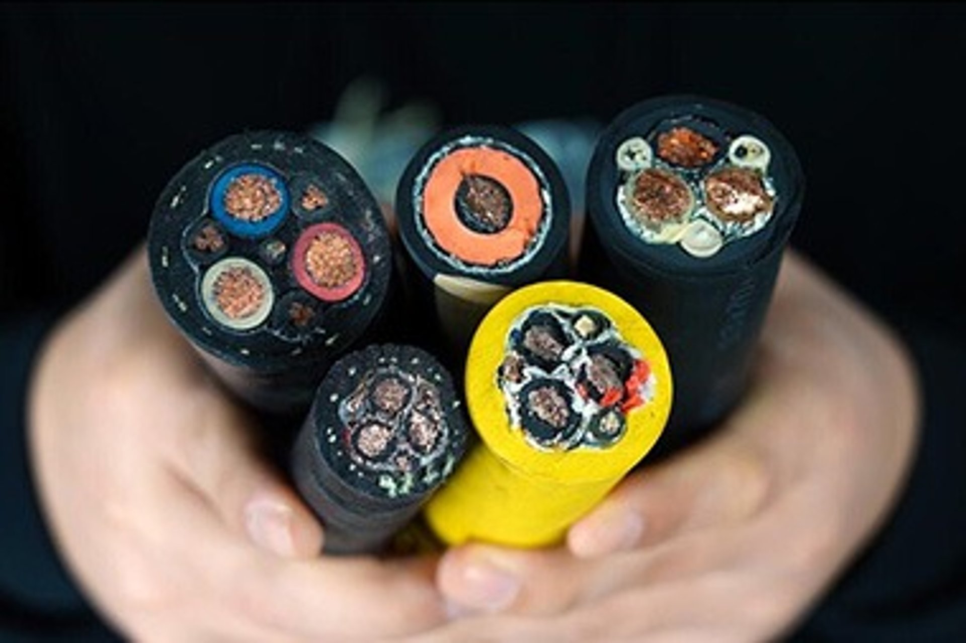
The three core cables are designed for distribution of electrical power with nominal voltage Uo/U ranging from 3.6/6.6KV to 19/33KV and frequency 50Hz. They are suitable for installation mostly in power supply stations, indoors and in cable ducts, outdoors, underground and in water as well as for installation on cable trays for industries, switchboards and power stations.
Standards
BS 6622
BS 7835 (LSZH Version)
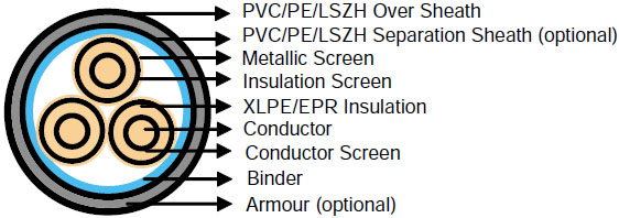
Construction
Conductor : Plain annealed copper or aluminium complying with IEC 60228/BS 6360. Copper conductors shall be stranded (class 2) and aluminium conductors shall be either solid or stranded (class 2).
Conductor Screen : Extruded layer of semi-conducting cross-linkable compound is applied over the conductor and shall cover the surface completely. The minimum thickness is 0.3mm and the maximum resistivity shall not exceed 500 Ohm-m at 90°C.
Insulation : Insulation is of cross-linked polyethylene compound XLPE (GP8) conforming to BS 7655-1.3 or EPR (GP7), conforming to BS 7655-1.2.
Table 1. Insulation Thickness
Nom. Cross Section Area | Insulation Thickness at Nominal Voltage | ||||
|---|---|---|---|---|---|
3.8/6.6KV (Um=7.2KV) | 6.35/11KV (Um=12KV) | 8.7/15KV(Um=17.5KV) | 12.7/22KV(Um=24KV) | 19/33KV(Um=36KV) | |
mm² | mm | mm | mm | mm | mm |
70 – 185 | 2.5 | 3.4 | 4.5 | 5.5 | 8.0 |
240 | 2.6 | 3.4 | 4.5 | 5.5 | 8.0 |
300 | 2.8 | 3.4 | 4.5 | 5.5 | 8.0 |
400 | 3.0 | 3.4 | 4.5 | 5.5 | 8.0 |
Above 500 | 3.2 | 3.4 | 4.5 | 5.5 | 8.0 |
Insulaton Screen : Extruded layer of semi-conducting cross-linkable compound is applied over the insulation. The extruded semi-conducting layer shall consist of bonded or cold strippable semi-conducting compound capable of removal for jointing or terminating. As anoption, a semi-conducting tape may be applied over the extruded semi-conducting layer as a bedding for the metallic layer. The minimum thickness is 0.3 mm and the maximum resistivity is 500 Ohm-m at 90°C. The screen is tightly fitted to the insulation to exclude all air voids and can be easily hand stripped on site.
Inner Covering & Fillers : For cables with a collective metallic layer or cables with a metallic layer over each individual cores with additional collective metallic layers, semi-conducting inner covering and fillers shall be applied over the laid up cores. The inner covering is made of non hygroscopic material, except if the cable is to be made longitudinally watertight. The inner covering shall be extruded or lapped.
The approximate thickness of extruded inner coverings is given in Table 2 :
Table 2. Approximate Thickness of Extruded Inner Coverings
Ficititous Diameter over Laid Up Cores | Approx. Thickness of Extruded Inner Covering | |
|---|---|---|
mm | mm | |
> | < |
|
- | 25 | 1.0 |
25 | 35 | 1.2 |
35 | 45 | 1.4 |
45 | 60 | 1.6 |
60 | 80 | 1.8 |
80 | - | 2.0 |
*The approximate thickness of lapped inner coverings shall be 0.6mm.
Metallic Layer : The metallic layer shall be applied over each core or applied as a collective screen. The metallic screen shall consist of either copper tapes or a concentric layer of copper wires or a combination of tapes and wires. The metallic layer provides an earth fault current path, capable of withstanding fault current to earth of 1000A for one second at maximum temperature 160°C. Copper wires are applied over the conducting water blocking layer with a minimum diameter of 0.5mm. As an alternative, copper tape(s) with minimum thickness of 0.1mm can be applied with overlap. Total cross section of copper wire screen and copper tape screen layer are shown in Table 3a and 3b.
Table 3a. Total Cross Section and Max. DC Resistance of Copper Wire Screen
Nominal Cross-Section of Cables | Total Cross Section | Max. DC Resistance of Copper Wire Screen at 20℃ | ||||
|---|---|---|---|---|---|---|
3.8/6.6KV (Um=7.2KV) | 6.35/11KV (Um=12KV) | 8.7/15KV (Um=17.5KV) | 12.7/22KV (Um=24KV) | 19/33KV (Um=36KV) | ||
mm² | mm² | Ω | ||||
70 | 16 | 16 | 16 | 16 | 16 | 1.19 |
95 | 16 | 16 | 16 | 16 | 16 | 1.19 |
120 | 16 | 16 | 16 | 16 | 16 | 1.19 |
150 | 25 | 25 | 25 | 25 | 25 | 0.759 |
185 | 25 | 25 | 25 | 25 | 25 | 0.759 |
240 | 25 | 25 | 25 | 25 | 25 | 0.759 |
300 | 25 | 25 | 25 | 25 | 25 | 0.759 |
400 | 35 | 35 | 35 | 35 | 35 | 0.271 |
500 | 35 | 35 | 35 | 35 | 35 | 0.271 |
630 | 35 | 35 | 35 | 35 | 35 | 0.271 |
Table 3b. Total Cross Section and Max. DC Resistance of Copper Tape Screen (0.1mm)
Nominal Cross-Section of Cables | Total Cross Section & Max DC Resistance | |||||||||
|---|---|---|---|---|---|---|---|---|---|---|
3.8/6.6KV (Um=7.2KV) | 6.35/11KV (Um=12KV) | 8.7/15KV (Um=17.5KV) | 12.7/22KV (Um=24KV) | 19/33KV (Um=36KV) | ||||||
Total Cross Section | Max. DC Resistance at 20℃ | Total Cross Section | Max. DC Resistance at 20℃ | Total Cross Section | Max. DC Resistance at 20℃ | Total Cross Section | Max. DC Resistance at 20℃ | Total Cross Section | Max. DC Resistance at 20℃ | |
mm² | mm² | Ω | mm² | Ω | mm² | Ω | mm² | Ω | mm² | Ω |
70 | 6.6 | 2.616 | 7.23 | 2.380 | 8.02 | 2.145 | 8.7 | 1.967 | 10.5 | 1.075 |
95 | 7.3 | 2.369 | 7.91 | 2.174 | 8.71 | 1.975 | 9.4 | 1.824 | 11.2 | 1.075 |
120 | 8.0 | 2.153 | 8.64 | 1.991 | 9.43 | 1.823 | 10.2 | 1.694 | 12.0 | 1.075 |
150 | 8.5 | 2.013 | 9.19 | 1.871 | 9.99 | 1.722 | 10.7 | 1.606 | 12.5 | 0.688 |
185 | 9.4 | 1.838 | 9.88 | 1.741 | 10.82 | 1.590 | 11.4 | 1.509 | 13.2 | 0.688 |
240 | 10.4 | 1.656 | 10.96 | 1.569 | 11.76 | 1.463 | 12.5 | 1.378 | 14.3 | 0.688 |
300 | 11.4 | 1.508 | 11.84 | 1.452 | 12.64 | 1.361 | 13.4 | 1.287 | 15.2 | 0.688 |
400 | 12.6 | 1.362 | 12.92 | 1.332 | 13.71 | 1.254 | 14.4 | 1.192 | 16.2 | 0.491 |
500 | 13.9 | 1.237 | 14.34 | 1.199 | 15.14 | 1.136 | 15.5 | 1.110 | 17.7 | 0.491 |
630 | 15.3 | 1.121 | 16.68 | 1.031 | 16.57 | 1.038 | 17.3 | 0.995 | 19.1 | 0.491 |
Separation Sheath (for armoured cable) : The separation sheath comprises a layer of extruded PVC, PE or LSZH. The nominal thickness is calculated by 0.02Du + 0.6mm where Du is the fictitious diameter under the sheath in mm. The nominal separation sheath thickness shall not be less than 1.2mm.
Armour (for armoured cable) : The armour consists of galvanized steel wire applied over the inner covering with diameter specified as in Table 4.
Table 4. Armour Wire Diameter
Fictitiious Diameter under the Armour | Armour Wire Diameter | |
|---|---|---|
mm | mm | |
> | < |
|
- | 25 | 1.6 |
25 | 35 | 2.0 |
35 | 60 | 2.5 |
60 | - | 3.15 |
Over Sheath : Overall sheath comprises a layer of extruded either PVC type 9 conforming to BS 7665-4.2 or MDPE type TS2 conforming to BS 7655-10.1; LSZH can be offered as an option. The over sheath is normally black in colour. When a DC voltage test is to be performed on the over sheath, a semi-conducting layer such as graphite coating shall be applied over the surface of the extruded over sheath. The nominal over sheath thickness is calculated by 0.035D+1 where D is the diameter immediately under the over sheath in mm. For cables with the over sheath not applied over the armour, the nominal over sheath thickness shall not be less than 1.4mm. And for cables with over sheath applied over the armour, the nominal over sheath thickness shall not be less than 1.8mm.
Understanding BS 6622 and BS 7835 Standards
The British Standards BS 6622 and BS 7835 define the construction and performance requirements for Three Core Cables. BS 6622 applies to standard cables, while BS 7835 specifies the Low Smoke Zero Halogen (LSZH) version, which minimizes toxic emissions in case of fire, enhancing safety in confined spaces like mining tunnels. These standards ensure that the cables meet stringent criteria for durability, electrical performance, and safety, making them suitable for high-voltage applications in industries such as mining, power generation, and heavy manufacturing.
Key Features of the Standards
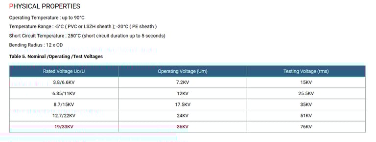
Voltage Range: Supports nominal voltages from 3.6/6.6 kV (Um=7.2 kV) to 19/33 kV (Um=36 kV).
Conductor Materials: Available in plain annealed copper or aluminum, with copper being stranded (class 2) and aluminum either solid or stranded.
Insulation: Utilizes cross-linked polyethylene (XLPE) or ethylene propylene rubber (EPR), both conforming to BS 7655 standards for excellent thermal and electrical properties.
Safety Compliance: BS 7835 LSZH cables are critical in environments where fire safety is paramount, such as underground mining operations.
Benefits of Three Core Cables
Three Core Cables to BS 6622 and BS 7835 offer numerous advantages, particularly in South Africa's industrial context:
Reliability: Their robust construction ensures consistent power delivery in harsh environments like mines and power stations.
Versatility: Suitable for diverse installation scenarios, including underground, underwater, and cable trays.
Safety: The LSZH option (BS 7835) reduces risks in fire-prone areas, critical for underground mining.
Durability: High-quality insulation and armour protect against mechanical and environmental stresses.
Efficiency: Low resistance and high current-carrying capacity optimize power transmission.
Usage Scenarios in South Africa
South Africa's mining and heavy industry sectors rely heavily on Three Core Cables due to their ability to withstand extreme conditions. Below are two case studies illustrating their application.
Conclusion
Three Core Cables to BS 6622 and BS 7835 are indispensable for powering South Africa's mining and heavy industry sectors. Their robust construction, compliance with stringent standards, and versatility make them ideal for challenging environments. By understanding their technical specifications, benefits, and installation requirements, industries can enhance operational efficiency and safety. As South Africa navigates energy and safety challenges, these cables will continue to play a critical role in sustaining industrial growth.