Three Core Cables to IEC 60502
Comprehensive Guide to Three Core Cables Compliant with IEC 60502
Three Core Cables to IEC 60502
Application
The three core cables are designed for distribution of electrical power with nominal voltage Uo/U ranging from 1.8/3KV to 26/35KV and frequency 50Hz. They are suitable for installation mostly in power supply stations, indoors and in cable ducts, outdoors, underground and in water as well as for installation on cable trays for industries, switchboards and power stations.
Standards
IEC 60502 Part 1(1.8/3KV)
IEC 60502 Part 2(3.6/6KV to 18/30KV)
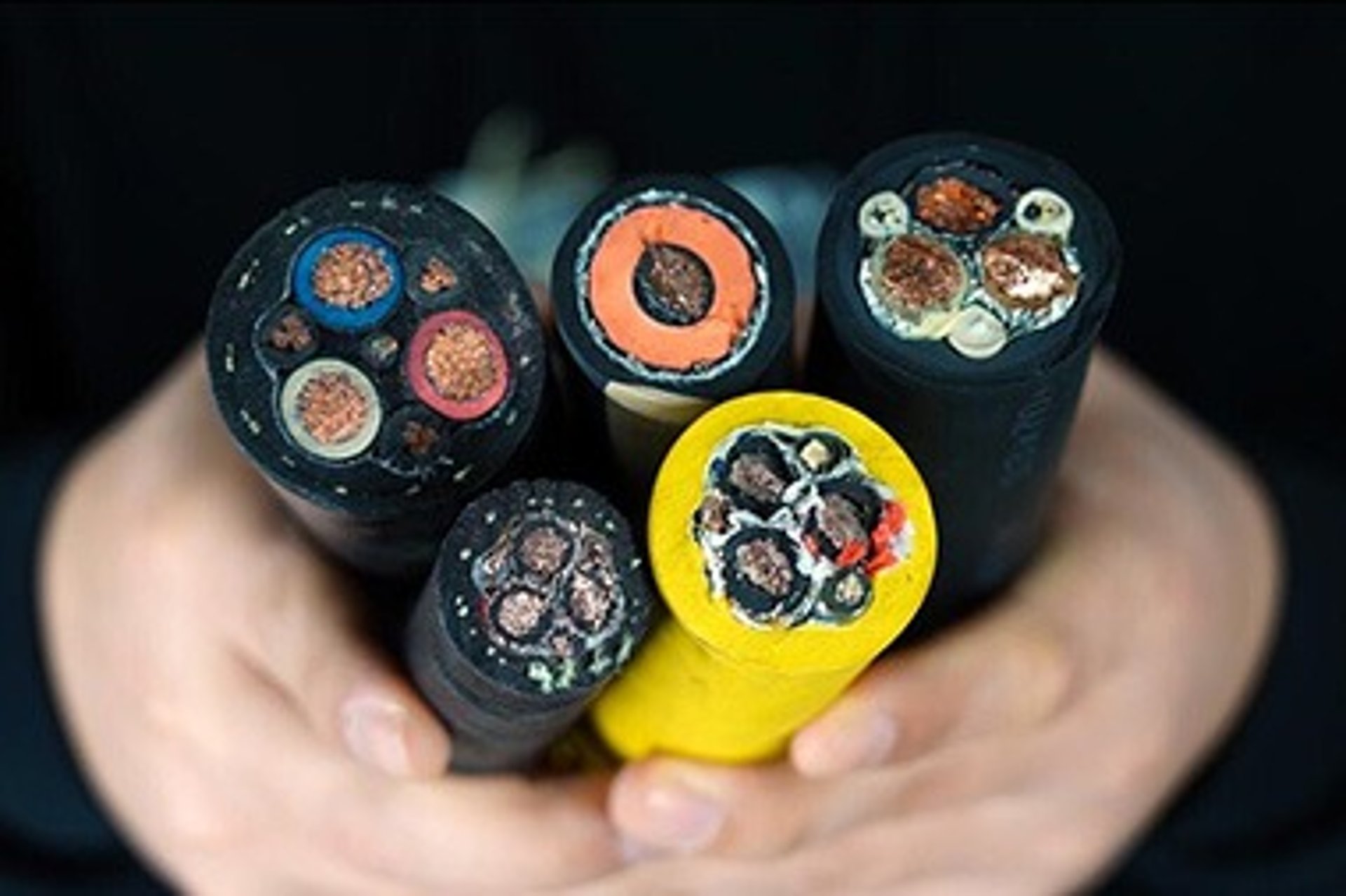
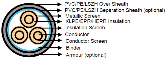
Construction
Conductor : Plain annealed copper or aluminium complying with IEC 60228 class 1 or 2.
Conductor Screen : The conductor screen consists of an extruded layer of non metallic, semi-conducting compound applied on top of a semi-conducting tape. The conductor screen is applied under triple extrusion process over the conductor along with the insulation and the insulation screen. The extruded semi-conducting compound is firmly bonded to the insulation to exclude all air voids and can be easily hand stripped on site. The conductor screen is not necessary for both PVC and EPR/HEPR insulated 1.8/3.6KV and 3.6/6KV cables.
Insulation : Insulation is of polyvinyl chloride (PVC) intended for 1.8/3.6KV and 3.6/6KV cables, cross-linked polyethylene compound (XLPE) or ethylene propylene rubber (EPR/HEPR).
Table 1. Insulation Thickness of XLPE or EPR/HEPR Insulation
Nom. Cross Section Area | Insulation Thickness at Nom. Voltage | |||||||
|---|---|---|---|---|---|---|---|---|
1.8/3kV (Um=3.6)kV | 3.6/6kV (Um=7.2)kV | 6/10KV (Um=12KV) | 8.7/15KV (Um=17KV) | 12/20KV (Um=24KV) | 18/30KV (Um=36KV) | |||
mm² | mm | mm | mm | mm | mm | mm | ||
| XLPE/EPR | XLPE | EPR | XLPE/EPR | XLPE/EPR | XLPE/EPR | XLPE/EPR | |
Unscreened | Screened | |||||||
10 | 2.0 | 2.5 | 3.0 | 2.5 | - | - | - | - |
16 | 2.0 | 2.5 | 3.0 | 2.5 | 3.4 | - | - | - |
25 | 2.0 | 2.5 | 3.0 | 2.5 | 3.4 | 4.5 | - | - |
35 | 2.0 | 2.5 | 3.0 | 2.5 | 3.4 | 4.5 | 5.5 | - |
50 – 185 | 2.0 | 2.5 | 3.0 | 2.5 | 3.4 | 4.5 | 5.5 | 8.0 |
240 | 2.0 | 2.6 | 3.0 | 2.6 | 3.4 | 4.5 | 5.5 | 8.0 |
300 | 2.0 | 2.8 | 3.0 | 2.8 | 3.4 | 4.5 | 5.5 | 8.0 |
400 | 2.0 | 3.0 | 3.0 | 3.0 | 3.4 | 4.5 | 5.5 | 8.0 |
500 - 1600 | 2.2-2.8 | 3.2 | 3.2 | 3.2 | 3.4 | 4.5 | 5.5 | 8.0 |
Insulaton Screen : The insulation screen consists of an extruded layer of non metallic, semi-conducting compound extruded over the insulation of each core. The extruded semi-conducting layer shall consist of bonded or cold strippable semi-conducting compound capable of removal for jointing or terminating. As an option, a semi-conducting tape may be applied over the individual cores or core assembly as a bedding for the metallic layer. The minimum thickness is 0.3 mm and the maximum resistivity is 500 Ohm-m at 90°C. The screen is tightly fitted to the insulation to exclude all air voids and can be easily hand stripped on site. The insulation screen is not necessary for both PVC and EPR/HEPR insulated 1.8/3.6KV and 3.6/6KV cables. The screen may be covered by semi-conductive water blocking swellable tape to ensure longitudinal watertightness.
Inner Covering & Fillers : For cables with a collective metallic layer or cables with a metallic layer over each individual cores with additional collective metallic layers, semi-conducting inner covering and fillers shall be applied over the laid up cores. The inner covering and fillers are made of non hygroscopic material like polypropylene, except if the cable is to be made longitudinally watertight. The inner covering is extruded in general but may be lapped if the interstices between the cores are filled.
The approximate thickness of extruded inner coverings is given in Table 2:
Table 2. Approximate Thickness of Extruded Inner Coverings
Ficititous Diameter Over Laid Up Cores | Approx. Thickress of Extruded Inner Covering | |
|---|---|---|
mm | mm | |
> | < |
|
- | 25 | 1.0 |
25 | 35 | 1.2 |
35 | 45 | 1.4 |
45 | 60 | 1.6 |
60 | 80 | 1.8 |
80 | - | 2.0 |
*The approximate thickness of lapped inner coverings shall be 0.4mm for fictitious diameters over the laid up cores up to and including 40mm and 0.6mm for larger diameter.
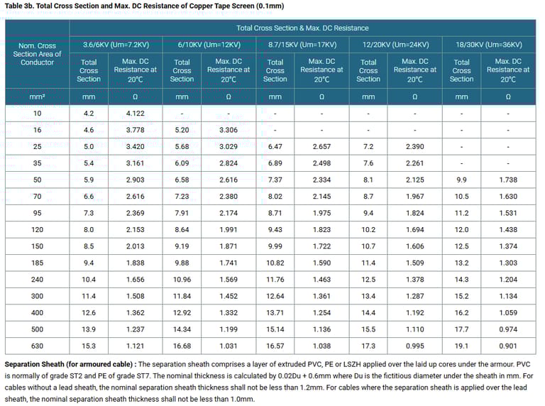
Metallic Layer : The concentric copper screen wire is applied over the insulation, or over the insulation screen or over an inner covering. As an alternative, copper tape(s) with minimum thickness of 0.1mm can be applied with overlap. Total cross section of copper wire screen and copper tape screen layer are shown in Table 3a and 3b.
Table 3a. Total Cross Section and Max. DC Resistance of Copper Wire Screen
Nom. Cross Section Area of Conductor | Total Cross Section | Max. DC Resistance at 20℃ | ||||
|---|---|---|---|---|---|---|
3.6/6KV (Um=7.2KV) | 6/10KV (Um=12KV) | 8.7/15KV (Um=17KV) | 12/20KV (Um=24KV) | 18/30KV (Um=36KV) | ||
mm² | mm | mm | mm | mm | mm | Ω |
10 | 10 | - | - | - | - | 1.075 |
16 | 16 | 16 | - | - | - | 1.075 |
25 | 16 | 16 | 16 | 16 | - | 1.075 |
35 | 16 | 16 | 16 | 16 | - | 1.075 |
50 | 16 | 16 | 16 | 16 | 16 | 1.075 |
70 | 16 | 16 | 16 | 16 | 16 | 1.075 |
95 | 16 | 16 | 16 | 16 | 16 | 1.075 |
120 | 16 | 16 | 16 | 16 | 16 | 1.075 |
150 | 25 | 25 | 25 | 25 | 25 | 0.688 |
185 | 25 | 25 | 25 | 25 | 25 | 0.688 |
240 | 25 | 25 | 25 | 25 | 25 | 0.688 |
300 | 25 | 25 | 25 | 25 | 25 | 0.688 |
400 | 35 | 35 | 35 | 35 | 35 | 0.491 |
500 | 35 | 35 | 35 | 35 | 35 | 0.491 |
630 | 35 | 35 | 35 | 35 | 35 | 0.491 |
Understanding the IEC 60502 Standard
The IEC 60502 standard is divided into parts: Part 1 covers cables up to 1.8/3 kV, while Part 2 addresses higher voltages from 3.6/6 kV to 18/30 kV. It specifies construction, testing, and performance requirements for cables with extruded insulation like polyvinyl chloride (PVC), cross-linked polyethylene (XLPE), or ethylene propylene rubber (EPR/HEPR). This ensures compatibility across international markets, reducing risks in global supply chains.
Compliance with IEC 60502 guarantees that cables withstand environmental stresses, including moisture, mechanical damage, and temperature fluctuations. For instance, cables must pass rigorous tests for insulation integrity, conductor resistance, and short-circuit withstand capability. In regions like South Africa, where SANS (South African National Standards) often align with IEC norms, these cables integrate seamlessly into local regulations, supporting the country's push for improved energy infrastructure amid load shedding challenges.
As of 2025, with South Africa's energy sector undergoing transformation—evidenced by a $25 billion grid expansion project adding over 14,000 km of transmission lines—adopting IEC 60502-compliant cables aligns with goals for reliable, low-carbon power distribution. This standard not only enhances safety but also promotes interoperability in heavy industries, where downtime can cost millions.
Technical Specifications of Three Core Cables to IEC 60502
Three core cables under IEC 60502 feature a robust construction tailored for medium-voltage applications. The core components include:
Conductor: Made from plain annealed copper or aluminum, compliant with IEC 60228 Class 1 or 2. Cross-sections range from 10 mm² to 630 mm², allowing flexibility for various load requirements.
Conductor Screen: An extruded semi-conducting compound over a tape, applied via triple extrusion to eliminate air voids. This is optional for lower voltages but essential for higher ones to manage electrical stress.
Insulation: XLPE or EPR/HEPR for superior thermal and electrical properties, with PVC for lower voltages. Insulation thickness varies by voltage; for example, at 6/10 kV, it's 3.4 mm across most cross-sections, ensuring dielectric strength.
Nominal Cross-Section Area (mm²) | Insulation Thickness at 6/10 kV (mm) | Insulation Thickness at 18/30 kV (mm) |
|---|---|---|
50-185 | 3.4 | 8.0 |
240 | 3.4 | 8.0 |
300 | 3.4 | 8.0 |
400 | 3.4 | 8.0 |
500-630 | 3.4 | 8.0 |
Insulation Screen: Similar semi-conducting layer, with a minimum thickness of 0.3 mm and resistivity up to 500 Ohm-m at 90°C, facilitating easy stripping during jointing.
Metallic Layer: Concentric copper wires or tapes for screening, with cross-sections detailed in tables. For 6/10 kV, copper wire screens are typically 16 mm² for smaller conductors, rising to 35 mm² for larger ones.
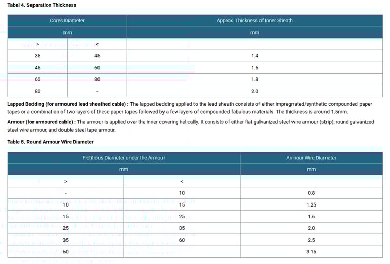
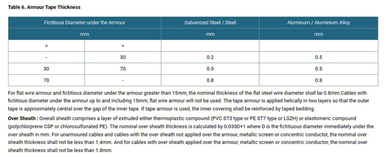
Armour (Optional): Galvanized steel wires or tapes for mechanical protection, crucial in underground or exposed installations. Round wire diameters range from 0.8 mm to 3.15 mm based on cable diameter.
Outer Sheath: PVC, PE, or LSZH (Low Smoke Zero Halogen) for environmental resistance, with thickness calculated as 0.035D + 1 mm (D being the under-sheath diameter), minimum 1.4 mm for unarmoured cables.
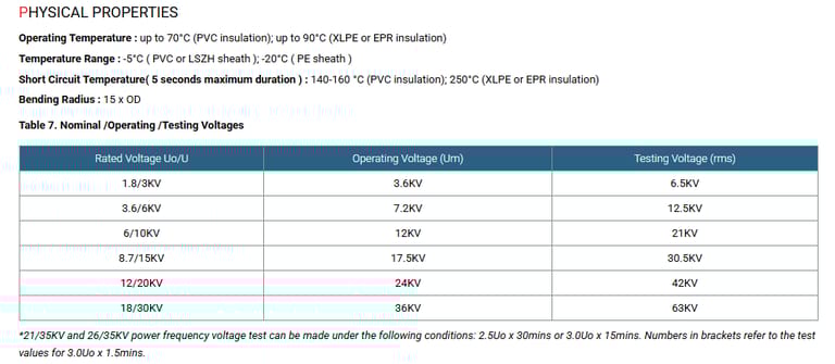
Physical properties include operating temperatures up to 90°C for XLPE/EPR, short-circuit ratings up to 250°C for 5 seconds, and bending radii of 15 times overall diameter. Electrical data encompasses DC/AC resistance, capacitance, and reactance, ensuring low losses.
For example, a 95 mm² copper conductor at 6/10 kV has a DC resistance of 193 µΩ/m, short-circuit rating of 13.3 kA (1 sec), and capacitance of 334 pF/m. These specs make the cables ideal for high-demand scenarios, with current ratings up to 663 A for 630 mm² in ground-laid unarmoured setups.
In South Africa's context, where mining cables must endure harsh conditions, armored variants align with trends toward durable, armored mining cables growing at 7.3% CAGR globally.
Benefits of Three Core Cables to IEC 60502
The advantages of these cables extend beyond compliance. Their extruded insulation provides excellent resistance to water, chemicals, and abrasion, reducing failure rates in wet or corrosive environments like mines. XLPE insulation, in particular, offers higher thermal ratings, allowing greater current-carrying capacity—up to 20% more than PVC—leading to energy savings.
Safety is enhanced through semi-conducting screens that manage voltage stress, preventing partial discharges. Armoured options protect against mechanical damage, vital in heavy industry where cables face impacts or rodent attacks. Environmentally, LSZH sheaths minimize toxic emissions in fires, aligning with green building standards.
Economically, longevity (up to 40 years) lowers replacement costs, while standardization reduces procurement complexities. In South Africa, amid a wires and cables market projected to reach $15.5 billion by 2030 at 5.5% CAGR, these cables support the shift to renewables, as mining firms integrate solar and wind to counter Eskom's 12.74% tariff hike in 2025. Benefits include reduced downtime, with studies showing 30% fewer outages in IEC-compliant systems.
Usage Scenarios and Case Studies in South Africa
Three core cables to IEC 60502 excel in power supply stations, indoor/outdoor installations, and underground networks. In mining, they distribute power to drills, conveyors, and lighting, handling voltages up to 18/30 kV.
South Africa's mining sector, a global leader in platinum and gold, faces energy insecurity from load shedding. With the industry turning to renewables—over 50% of mines investing in solar by 2025—these cables facilitate hybrid grids. The $1.5 billion World Bank loan for green infrastructure underscores this shift.
Three core cables to IEC 60502 represent a blend of innovation and reliability, essential for powering the future. From technical prowess to real-world applications in South Africa's evolving energy landscape, they offer solutions to pressing challenges. As industries adopt sustainable practices, these cables will continue to drive efficiency and resilience. For professionals in mining or heavy sectors, investing in IEC-compliant technology isn't just smart—it's imperative for a powered tomorrow.