
Three Core Cables to IEC 60502
Application
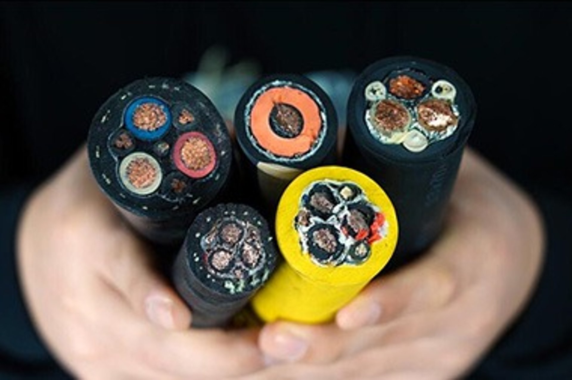
The three core cables are designed for distribution of electrical power with nominal voltage Uo/U ranging from 1.8/3KV to 26/35KV and frequency 50Hz. They are suitable for installation mostly in power supply stations, indoors and in cable ducts, outdoors, underground and in water as well as for installation on cable trays for industries, switchboards and power stations.
Standards
IEC 60502 Part 1(1.8/3KV)
IEC 60502 Part 2(3.6/6KV to 18/30KV)
Construction
Conductor : Plain annealed copper or aluminium complying with IEC 60228 class 1 or 2.
Conductor Screen : The conductor screen consists of an extruded layer of non metallic, semi-conducting compound applied on top of a semi-conducting tape. The conductor screen is applied under triple extrusion process over the conductor along with the insulation and the insulation screen. The extruded semi-conducting compound is firmly bonded to the insulation to exclude all air voids and can be easily hand stripped on site. The conductor screen is not necessary for both PVC and EPR/HEPR insulated 1.8/3.6KV and 3.6/6KV cables.
Insulation : Insulation is of polyvinyl chloride (PVC) intended for 1.8/3.6KV and 3.6/6KV cables, cross-linked polyethylene compound (XLPE) or ethylene propylene rubber (EPR/HEPR).
Table 1. Insulation Thickness of XLPE or EPR/HEPR Insulation
Nom. Cross Section Area | Insulation Thickness at Nom. Voltage | |||||||
|---|---|---|---|---|---|---|---|---|
1.8/3kV (Um=3.6)kV | 3.6/6kV (Um=7.2)kV | 6/10KV (Um=12KV) | 8.7/15KV (Um=17KV) | 12/20KV (Um=24KV) | 18/30KV (Um=36KV) | |||
mm² | mm | mm | mm | mm | mm | mm | ||
| XLPE/EPR | XLPE | EPR | XLPE/EPR | XLPE/EPR | XLPE/EPR | XLPE/EPR | |
Unscreened | Screened | |||||||
10 | 2.0 | 2.5 | 3.0 | 2.5 | - | - | - | - |
16 | 2.0 | 2.5 | 3.0 | 2.5 | 3.4 | - | - | - |
25 | 2.0 | 2.5 | 3.0 | 2.5 | 3.4 | 4.5 | - | - |
35 | 2.0 | 2.5 | 3.0 | 2.5 | 3.4 | 4.5 | 5.5 | - |
50 – 185 | 2.0 | 2.5 | 3.0 | 2.5 | 3.4 | 4.5 | 5.5 | 8.0 |
240 | 2.0 | 2.6 | 3.0 | 2.6 | 3.4 | 4.5 | 5.5 | 8.0 |
300 | 2.0 | 2.8 | 3.0 | 2.8 | 3.4 | 4.5 | 5.5 | 8.0 |
400 | 2.0 | 3.0 | 3.0 | 3.0 | 3.4 | 4.5 | 5.5 | 8.0 |
500 - 1600 | 2.2-2.8 | 3.2 | 3.2 | 3.2 | 3.4 | 4.5 | 5.5 | 8.0 |
Insulaton Screen : The insulation screen consists of an extruded layer of non metallic, semi-conducting compound extruded over the insulation of each core. The extruded semi-conducting layer shall consist of bonded or cold strippable semi-conducting compound capable of removal for jointing or terminating. As an option, a semi-conducting tape may be applied over the individual cores or core assembly as a bedding for the metallic layer. The minimum thickness is 0.3 mm and the maximum resistivity is 500 Ohm-m at 90°C. The screen is tightly fitted to the insulation to exclude all air voids and can be easily hand stripped on site. The insulation screen is not necessary for both PVC and EPR/HEPR insulated 1.8/3.6KV and 3.6/6KV cables. The screen may be covered by semi-conductive water blocking swellable tape to ensure longitudinal watertightness.
Inner Covering & Fillers : For cables with a collective metallic layer or cables with a metallic layer over each individual cores with additional collective metallic layers, semi-conducting inner covering and fillers shall be applied over the laid up cores. The inner covering and fillers are made of non hygroscopic material like polypropylene, except if the cable is to be made longitudinally watertight. The inner covering is extruded in general but may be lapped if the interstices between the cores are filled.
The approximate thickness of extruded inner coverings is given in Table 2:
Table 2. Approximate Thickness of Extruded Inner Coverings
Ficititous Diameter Over Laid Up Cores | Approx. Thickress of Extruded Inner Covering | |
|---|---|---|
mm | mm | |
> | < |
|
- | 25 | 1.0 |
25 | 35 | 1.2 |
35 | 45 | 1.4 |
45 | 60 | 1.6 |
60 | 80 | 1.8 |
80 | - | 2.0 |
*The approximate thickness of lapped inner coverings shall be 0.4mm for fictitious diameters over the laid up cores up to and including 40mm and 0.6mm for larger diameter.
Metallic Layer : The concentric copper screen wire is applied over the insulation, or over the insulation screen or over an inner covering. As an alternative, copper tape(s) with minimum thickness of 0.1mm can be applied with overlap. Total cross section of copper wire screen and copper tape screen layer are shown in Table 3a and 3b.
Table 3a. Total Cross Section and Max. DC Resistance of Copper Wire Screen
Nom. Cross Section Area of Conductor | Total Cross Section | Max. DC Resistance at 20℃ | ||||
|---|---|---|---|---|---|---|
3.6/6KV (Um=7.2KV) | 6/10KV (Um=12KV) | 8.7/15KV (Um=17KV) | 12/20KV (Um=24KV) | 18/30KV (Um=36KV) | ||
mm² | mm | mm | mm | mm | mm | Ω |
10 | 10 | - | - | - | - | 1.075 |
16 | 16 | 16 | - | - | - | 1.075 |
25 | 16 | 16 | 16 | 16 | - | 1.075 |
35 | 16 | 16 | 16 | 16 | - | 1.075 |
50 | 16 | 16 | 16 | 16 | 16 | 1.075 |
70 | 16 | 16 | 16 | 16 | 16 | 1.075 |
95 | 16 | 16 | 16 | 16 | 16 | 1.075 |
120 | 16 | 16 | 16 | 16 | 16 | 1.075 |
150 | 25 | 25 | 25 | 25 | 25 | 0.688 |
185 | 25 | 25 | 25 | 25 | 25 | 0.688 |
240 | 25 | 25 | 25 | 25 | 25 | 0.688 |
300 | 25 | 25 | 25 | 25 | 25 | 0.688 |
400 | 35 | 35 | 35 | 35 | 35 | 0.491 |
500 | 35 | 35 | 35 | 35 | 35 | 0.491 |
630 | 35 | 35 | 35 | 35 | 35 | 0.491 |