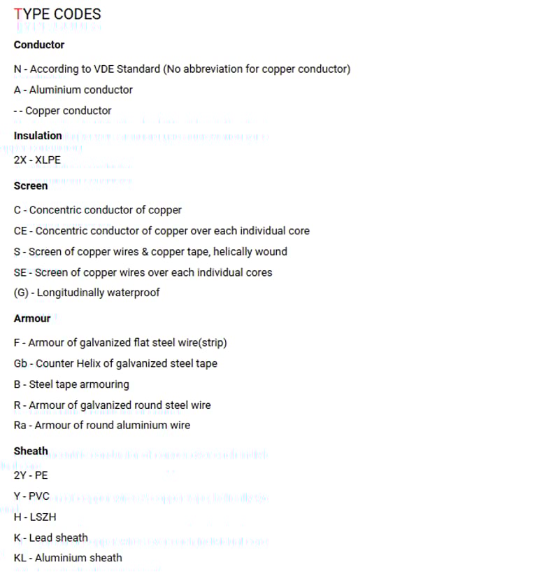

Three Core Cables to VDE 0276
Application
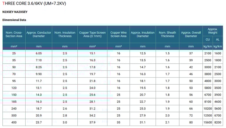
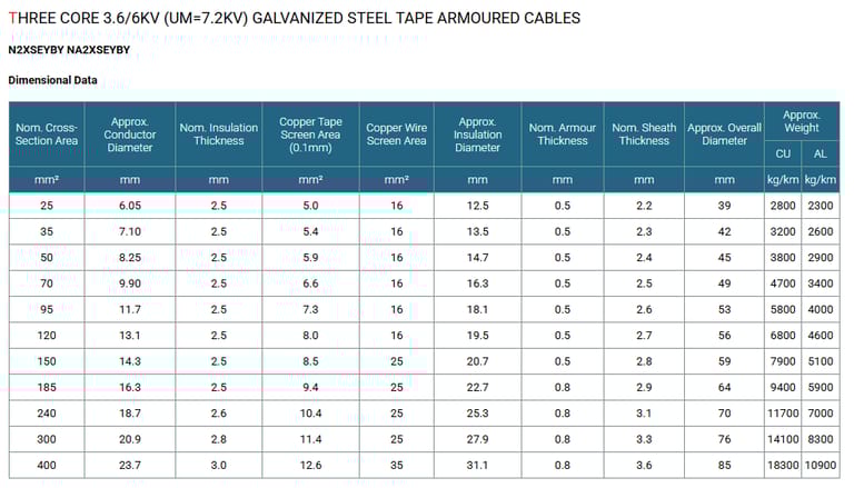
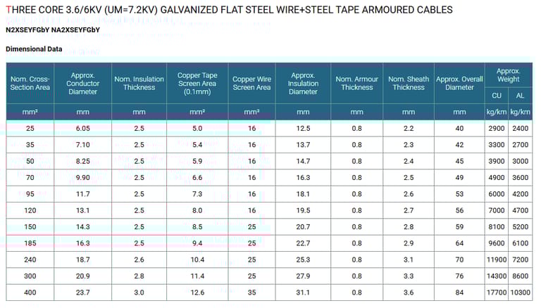
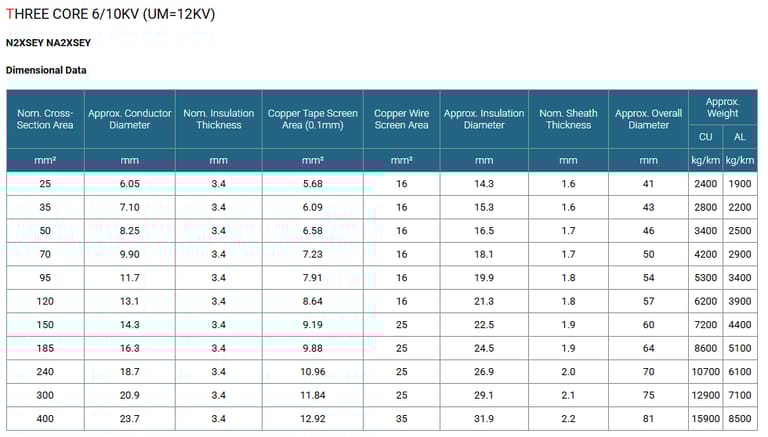
The three core cables are designed for distribution of electrical power with nominal voltage Uo/U ranging from 3.6/6KV to 18/30KV and frequency 50Hz. They are suitable for installation mostly in power supply stations, indoors and in cable ducts, outdoors, underground and in water as well as for installation on cable trays for industries, switchboards and power stations.
Standards
DIN VDE 0276 Part 620-622
HD 620 S1
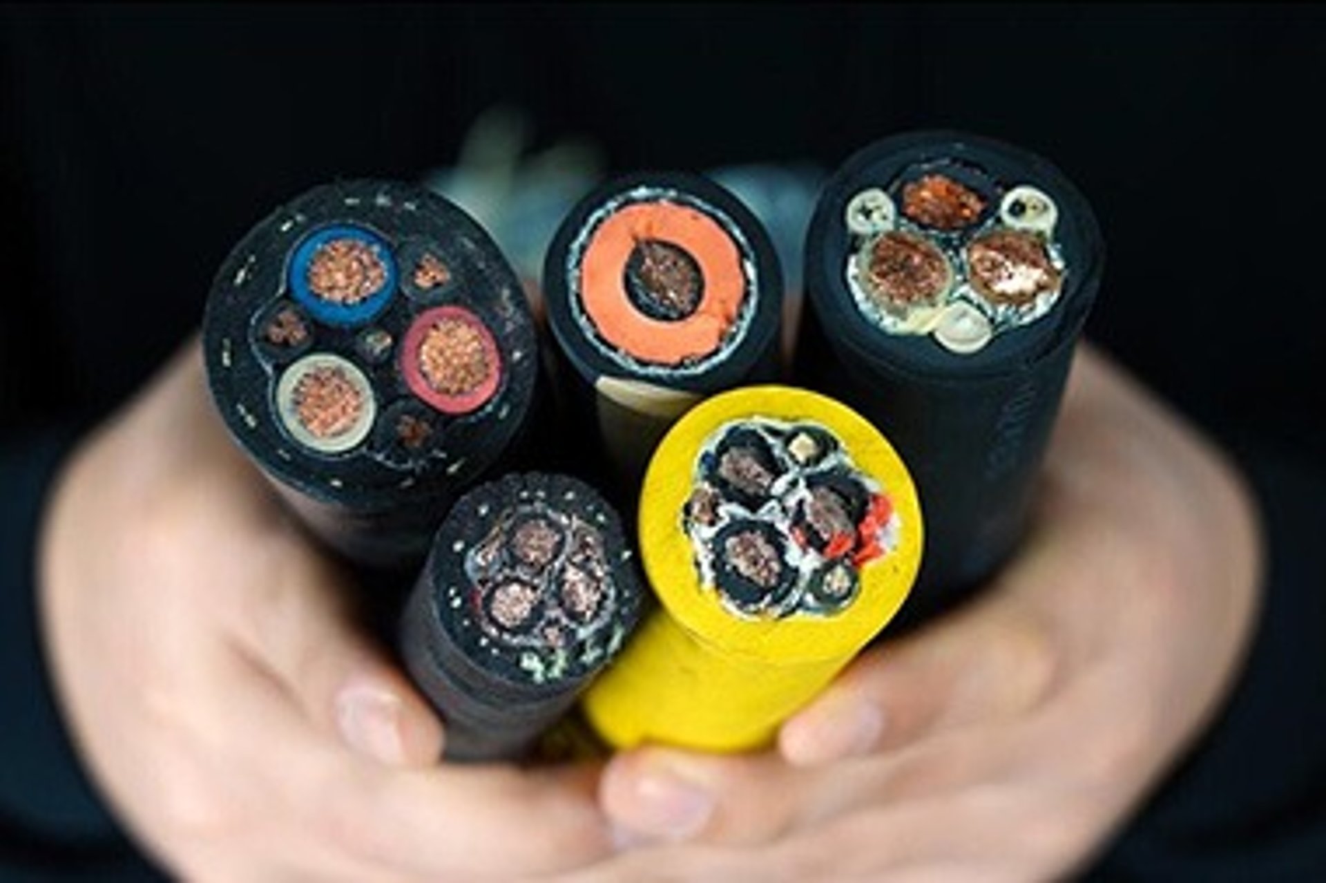
Construction
Conductor : Stranded compacted circular copper or aluminium conductors according to IEC 60228 class 2 / VDE 0276 class 2 / VDE 0295 HD 383. All internal interstices of the conductor are filled with water blocking compound to prevent ingress of water through conductor during storage, handing, installation and operating of the cable.
Conductor Screen : The conductor screen consists of an extruded layer of non metallic, semi-conducting compound firmly bonded to the insulation to exclude all air voids. The screen has a minimum thickness of 0.3mm and the maximum volume resistivity of 500 Ohm-m at 90°C.
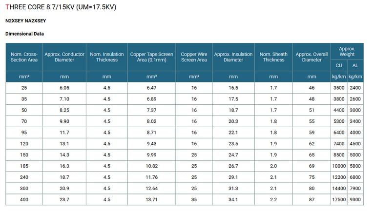
Insulation : Insulation is of extruded XLPE compound type 2XI1 according to DIN VDE 0207 part 22 and HD 620.1 with high degree of cross-linking, free from contaminants, air voids and heat resistant by dry cured process.
The nominal insulation wall thickness is shown in table 1.
Table 1. Insulation Thickness
Nom. Cross Section Area of Conductor | Insulation Thickness at Nom. Voltage | ||||
|---|---|---|---|---|---|
3.6/6KV(Um=7.2KV) | 6/10KV(Um=12KV) | 8.7/15KV(Um=17.5KV) | 12/20KV(Um=24KV) | 18/30KV(Um=36KV) | |
mm² | mm | mm | mm | mm | mm |
35 | 2.5 | 3.4 | 4.5 | 5.5 | - |
50 | 2.5 | 3.4 | 4.5 | 5.5 | 8.0 |
70 | 2.5 | 3.4 | 4.5 | 5.5 | 8.0 |
95 | 2.5 | 3.4 | 4.5 | 5.5 | 8.0 |
120 | 2.5 | 3.4 | 4.5 | 5.5 | 8.0 |
150 | 2.5 | 3.4 | 4.5 | 5.5 | 8.0 |
185 | 2.5 | 3.4 | 4.5 | 5.5 | 8.0 |
240 | 2.6 | 3.4 | 4.5 | 5.5 | 8.0 |
300 | 2.8 | 3.4 | 4.5 | 5.5 | 8.0 |
400 | 3.0 | 3.4 | 4.5 | 5.5 | 8.0 |
Insulation Screen : The insulation screen consists of extruded non metallic, semi-conducting compound extruded over the insulation. The extruded semi-conducting layer shall consist of bonded or cold strippable semi-conducting compound capable of removal for jointing or terminating.The minimum thickness is 0.3mm and the maximum volume resistivity of 500 Ohm-m at 90°C. The screen is tightly fitted to the insulation to exclude all air voids and can be easily hand stripped on site.
Conducting Water Blocking Layer : The insulation screen may be coverd by semiconductive water blocking tape which will swell up under the influence of moisture of water to ensure longitudinal watertightness.
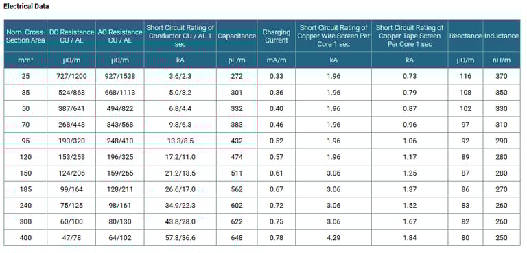
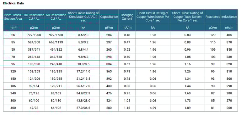
Metallic Layer : The metallic layer shall consist of either copper tapes or a concentric layer of copper wires or a combination of tapes and wires. The metallic layer provides an earth fault current path, capable of withstanding fault current to earth of 1000A for one second at maximum temperature 160°C. Copper wires are applied over the conducting water blocking layer with a minimum diameter of 0.5mm. As an alternative, copper tape(s) with minimum thickness of 0.1mm can be applied with overlap. Total cross section of copper wire screen and copper tape screen layer are shown in Table 2a and 2b.
Table 2a. Total Cross Section and Max. DC Resistance of Copper Wire Screen
Nominal Cross-Section of Cables | Total Cross Section | Max. DC Resistance of Copper Wire Screen at 20℃ | ||||
|---|---|---|---|---|---|---|
36/6KV (Um=7.2KV) | 6/10KV (Um=12KV) | 8.7/15KV (Um=17.5KV) | 12/20KV (Um=24KV) | 18/30KV (Um=36KV) | ||
mm² | mm² | Ω | ||||
70 | 16 | 16 | 16 | 16 | 16 | 1.19 |
95 | 16 | 16 | 16 | 16 | 16 | 1.19 |
120 | 16 | 16 | 16 | 16 | 16 | 1.19 |
150 | 25 | 25 | 25 | 25 | 25 | 0.759 |
185 | 25 | 25 | 25 | 25 | 25 | 0.759 |
240 | 25 | 25 | 25 | 25 | 25 | 0.759 |
300 | 25 | 25 | 25 | 25 | 25 | 0.759 |
400 | 35 | 35 | 35 | 35 | 35 | 0.271 |
500 | 35 | 35 | 35 | 35 | 35 | 0.217 |
630 | 35 | 35 | 35 | 35 | 35 | 0.271 |
Table 2b. Total Cross Section and Max. DC Resistance of Copper Tape Screen (0.1mm)
Nominal Cross-Section of Cables | Total Cross Section & Max. DC Resistance | |||||||||
|---|---|---|---|---|---|---|---|---|---|---|
3.6/6KV(Um=7.2KV) | 6/10KV(Um=12KV) | 8.7/15KV(Um=17.5KV) | 12/20KV(Um=24KV) | 18/30KV(Um=36KV) | ||||||
|
|
|
|
| ||||||
Total Cross Section | Max. DC Resistance at 20℃ | Total Cross Section | Max. DC Resistance at 20℃ | Total Cross Section | Max. DC Resistance at 20℃ | Total Cross Section | Max. DC Resistance at 20℃ | Total Cross Section | Max. DC Resistance at 20℃ | |
mm² | mm² | Ω | mm² | Ω | mm² | Ω | mm² | Ω | mm² | Ω |
70 | 6.6 | 2.616 | 7.23 | 2.380 | 8.02 | 2.145 | 8.7 | 1.967 | 10.5 | 1.075 |
95 | 7.3 | 2.369 | 7.91 | 2.174 | 8.71 | 1.975 | 9.4 | 1.824 | 11.2 | 1.075 |
120 | 8.0 | 2.153 | 8.64 | 1.991 | 9.43 | 1.823 | 10.2 | 1.694 | 12.0 | 1.075 |
150 | 8.5 | 2.013 | 9.19 | 1.871 | 9.99 | 1.722 | 10.7 | 1.606 | 12.5 | 0.688 |
185 | 9.4 | 1.838 | 9.88 | 1.741 | 10.82 | 1.590 | 11.4 | 1.509 | 13.2 | 0.688 |
240 | 10.4 | 1.656 | 10.96 | 1.569 | 11.76 | 1.463 | 12.5 | 1.378 | 14.3 | 0.688 |
300 | 11.4 | 1.508 | 11.84 | 1.452 | 12.64 | 1.361 | 13.4 | 1.287 | 15.2 | 0.688 |
400 | 12.6 | 1.362 | 12.92 | 1.332 | 13.71 | 1.254 | 14.4 | 1.192 | 16.2 | 0.491 |
500 | 13.9 | 1.237 | 14.34 | 1.199 | 15.14 | 1.136 | 15.5 | 1.110 | 17.7 | 0.491 |
630 | 15.3 | 1.121 | 16.68 | 1.031 | 16.57 | 1.038 | 17.3 | 0.995 | 19.1 | 0.491 |
Separator / Water Blocking Layer : The metallic screen may be covered by non-conducting water blocking tape which will swell up under the influence of moisture of water to ensure longitudinal watertightness.
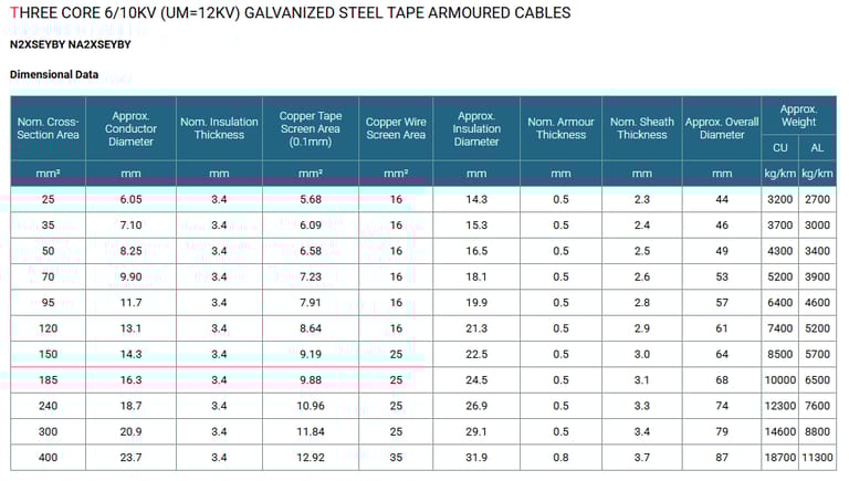
Separation Sheath (for armoured cable) : The separation sheath comprises a layer of extruded PVC, PE or LSZH, applied under the armour. Thickness of separation sheath as shown in table 3.
Table 3. Separation Sheath Thickness
Core Diameter | Approx.Thickess of Inner Sheath | |
|---|---|---|
mm | mm | |
> | < |
|
35 | 45 | 1.4 |
45 | 60 | 1.6 |
60 | 80 | 1.8 |
80 | - | 2.0 |
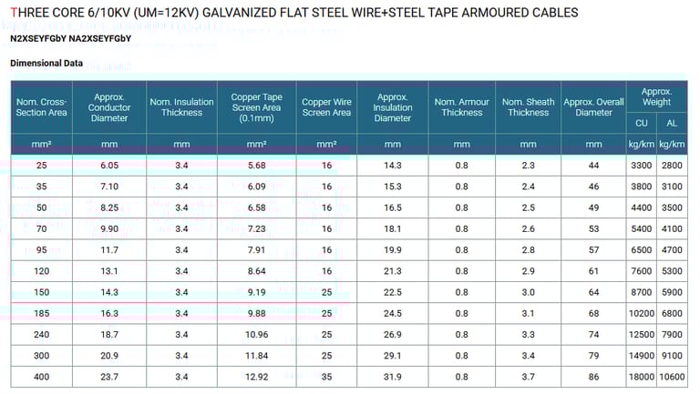
Armour(for armoured cable) :
The armour consists of :
1) Double layers of galvanized steel tape are applied helically with proper inner overlapping over an extruded separation sheath. Thickness of the steel tape is shown in table 4.