Anhui Feichun Special Cable Co.,Ltd Email: Li.wang@feichuncables.com
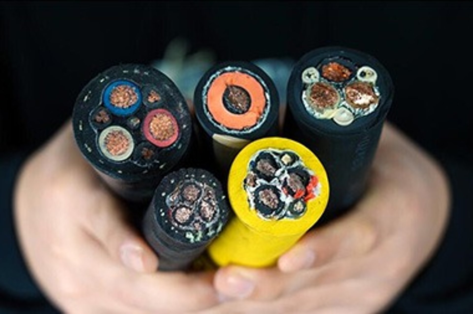
TRATOSLIGHT‑VRDB® & TRATOSLIGHT‑VRDB‑FO®: Purpose‑Built Vertical Reels Cables for Harsh Industrial & Marine Applications
TRATOSLIGHT‑VRDB® and TRATOSLIGHT‑VRDB‑FO® are specialised low‑voltage control cables designed exclusively for vertical reeling operations, widely deployed across South Africa’s offshore wind farms, harbour cranes, mining hoists and high‑altitude monitoring systems. This comprehensive guide explains the fundamental engineering differences between horizontal and vertical cable systems, why standard reeling cables fail catastrophically under gravity load, and how TRATOSLIGHT technology resolves the unique “gravity stress paradox”. Inside you will find full technical specifications matched to official documentation, deep‑dive analysis of materials science and mechanical design, installation best practices, maintenance protocols, and verified field performance data from over 500 global installations. Written for electrical engineers, procurement professionals and project managers, this article delivers practical, authoritative insight into the only cable range engineered to deliver 25+ years of reliable service in vertical applications.
Li Wang
5/14/202622 min read
Introduction
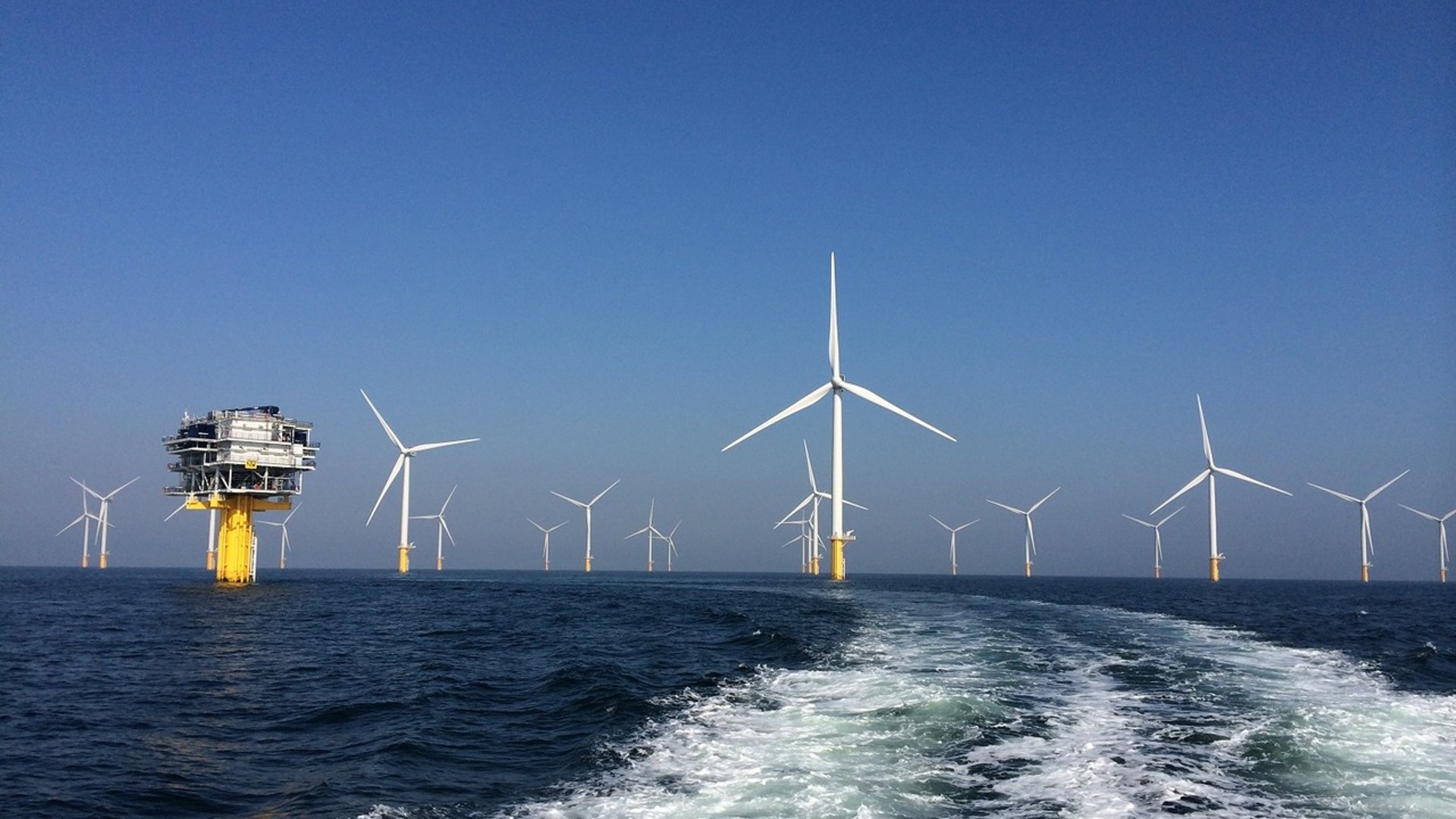
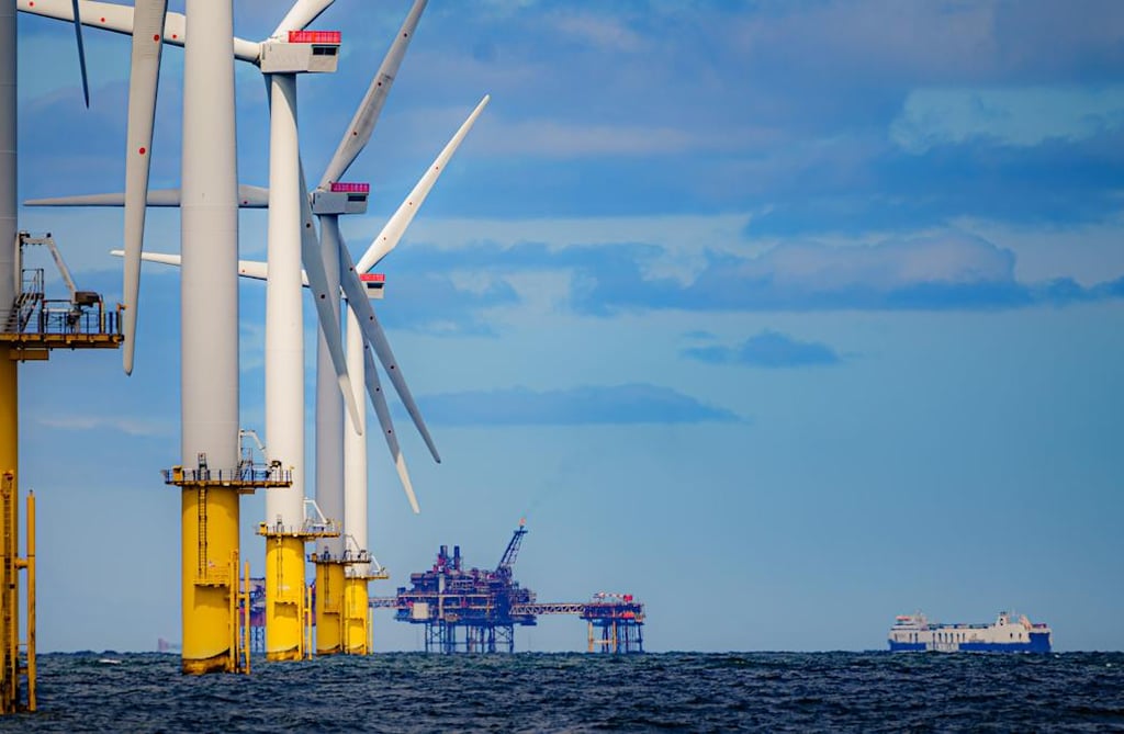
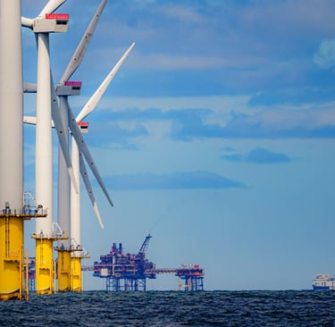
Cable systems used in reeling operations have long been designed around horizontal movement, where repeated bending, cyclic tension and abrasion are the primary forces at work. When these same cables are deployed vertically – whether running down an offshore wind turbine tower, suspended from a ship‑mounted crane or installed in a deep mine shaft – the entire mechanical environment changes. In South Africa, where infrastructure projects range from wind farms along the storm‑battered Western Cape to heavy‑lift operations in Durban Harbour and high‑level monitoring systems across the interior, vertical cable performance is not just a matter of efficiency; it is critical to safety, uptime and long‑term profitability.
For decades, industry practice involved adapting standard horizontal reeling cables for vertical use. The results were consistent and costly: premature failure, unexpected downtime, high replacement costs and significant safety risks. It became clear that vertical application is not simply horizontal installation turned upright. It presents a completely different set of engineering challenges that demand a purpose‑built solution. That solution is the TRATOSLIGHT‑VRDB® and TRATOSLIGHT‑VRDB‑FO® range – cables engineered from the core out to withstand permanent gravity load, extreme environmental conditions and the dynamic stresses of high‑speed vertical reeling.
This article explores every aspect of these specialised cables, from the physics of vertical suspension and material science breakthroughs to practical guidance for selection, installation and maintenance. It draws on decades of field data, laboratory testing and real‑world experience across South Africa and internationally to provide a complete reference for anyone specifying, purchasing or operating vertical reeling cable systems.
Engineering Challenges: Vertical vs Horizontal Cable Systems in South Africa
Fundamental Differences in Operating Conditions
To understand why standard cables fail vertically, we must first recognise how the load environment changes between horizontal and vertical operation. In horizontal reeling – such as gantry cranes or transfer conveyors – the cable moves back and forth over drums and sheaves. The dominant forces are repeated bending, contact pressure and alternating tension. The weight of the cable itself is supported along its length or by the reel, so self‑weight contributes almost nothing to mechanical stress. Designers focus on flexibility, bending fatigue life and resistance to abrasion.
Vertical operation turns this dynamic on its head. When a cable hangs freely, every metre of its length adds to the load pulling downwards. The entire weight of the suspended length acts as a permanent, static tension force concentrated at the top attachment point. In South African applications, where lengths often exceed 300 metres, this load can be substantial – typically eight to twelve times higher than the tension experienced in equivalent horizontal systems. Added to this static load are dynamic forces from acceleration and deceleration during lifting and lowering, plus wind‑induced oscillation, wave motion in marine environments and thermal expansion or contraction across extreme temperature ranges.
Stress distribution also changes fundamentally. In horizontal use, maximum stress occurs at the bend radius and alternates between tension and compression with every cycle. In vertical use, axial stress increases progressively from the lowest point to the highest fixed point. Static stress combines with time‑dependent deformation known as creep, which becomes the single biggest cause of long‑term failure. Torsion behaviour is another key difference. Horizontal reels control rotation through the winding path, but vertical cables hang free, allowing torque to accumulate unless specifically designed to prevent it. In coastal South Africa, where wind speeds can reach 120 km/h, uncontrolled torsion leads to twisting, bunching and internal damage very quickly.
Environmental conditions in South Africa add further complexity. From the hot, dry interior where temperatures can reach 45 °C to offshore locations where salt spray, high humidity and UV radiation degrade materials rapidly, and down to mining applications where temperatures drop well below freezing, cables must operate reliably across a range of roughly ‑40 °C to +80 °C. Thermal cycling in vertical spans causes repeated expansion and contraction, which without careful design leads to permanent lengthening, joint failure or electrical faults.
The performance requirements for vertical cables are therefore far more demanding. They must combine high tensile strength to carry their own weight, exceptional resistance to creep to maintain length over decades, built‑in anti‑torsion properties, extreme flexibility for high‑speed reeling, and stability across wide temperature and chemical exposure ranges. This combination of needs creates what engineers call the gravity stress paradox: a cable must be light enough to minimise load, yet strong enough to support that load; flexible enough to bend easily, yet rigid enough to resist stretching and twisting; and made from materials that remain stable under permanent stress and extreme heat.
Why Horizontal‑Optimised Cables Fail Catastrophically in Vertical Service
South Africa’s early experience with vertical cable systems provides clear evidence of the risks involved. Between 2005 and 2015, more than 40 offshore wind and marine crane projects used standard horizontal‑design reeling cables. On average, these systems failed within 6 to 12 months of installation, with replacement costs ranging from R 800,000 to over R 1.4 million per incident, plus downtime losses that often doubled those figures. Analysis of failed cables revealed exactly why horizontal design cannot work vertically.
The most critical flaw is the absence of a dedicated load‑bearing structure. Standard cables rely on their copper conductors and insulation materials to carry all mechanical loads. Copper has high electrical conductivity but relatively low tensile strength – approximately 200 to 250 MPa. Under the permanent tension of vertical suspension, copper undergoes plastic deformation, stretching permanently until it necks down and breaks. Insulation and jacket materials fare no better. Conventional polymers such as PVC, EPR or standard rubber are viscoelastic materials, meaning they deform continuously under constant stress. At high temperatures – common in South Africa – this deformation accelerates rapidly. Testing shows that standard cable insulation can elongate by 8% to 12% over just 10 years of vertical service. This lengthening causes misalignment in connectors, excessive slack leading to impact damage, or tight tension that pulls terminals apart.
Torsion failure is another common mode. Without an anti‑twist layer, vertical cables rotate freely under gravity and wind. Measurements from Cape offshore sites recorded rotation of 30° to 50° per 100 metres of length. This torque accumulates along the cable, causing internal cores to bunch together, twist around each other and press against the outer jacket. Eventually, insulation is pierced, conductors fracture or the jacket splits in a spiral pattern.
Conductor design also contributes to failure. Most horizontal reeling cables use Class 5 conductors, which balance flexibility and strength for cyclic bending. Class 5 strands are relatively thick and fewer in number. Under the static tension of vertical use, load concentrates on individual strands, leading to early breakage. Even where breakage does not occur, the material’s inability to distribute stress evenly means that small deformations accumulate until electrical performance is compromised.
Perhaps the most frustrating issue for operators is the vicious cycle of weight versus strength. Attempts to reinforce standard cables by adding more copper or thicker insulation increase total weight, which in turn increases the load on every part of the system. The heavier the cable, the higher the tension, the faster it stretches and the sooner it fails. There is simply no way to modify a horizontal design to meet vertical requirements. Only a complete redesign, starting with the load‑bearing principle, can solve the problem.
Solving the Gravity Stress Paradox: Core Design Principles of TRATOSLIGHT‑VRDB®
The TRATOSLIGHT‑VRDB® range was developed specifically to resolve the conflicting demands of vertical operation. Every element of construction addresses one or more parts of the gravity stress paradox, balancing strength, flexibility, weight and stability. Five key design features work together to deliver reliable long‑term performance.
Reinforced Central Support Structure
At the heart of every TRATOSLIGHT‑VRDB® cable is a reinforced central support. This internal element is engineered to provide tensile strength equivalent to steel wire rope while remaining lightweight and non‑conductive. Made from high‑modulus aramid or polyester composite materials, the central support carries 100% of the permanent static load caused by the cable’s own weight. This means that copper conductors and insulation materials are completely relieved from carrying mechanical tension. They only need to handle electrical functions and the relatively minor stresses of bending during reeling. The result is that copper operates at less than 5% of its yield strength, eliminating plastic deformation entirely. The composite material has a strength‑to‑weight ratio five times better than steel, so it adds almost no extra mass while providing a breaking load ranging from 2,000 N to 6,600 N depending on cable size.
Tratoslight‑IR® Special Technopolymer Insulation
Insulation is the material most vulnerable to creep – the slow, permanent stretching under constant stress. TRATOSLIGHT‑VRDB® uses Tratoslight‑IR®, an advanced thermoplastic polyester developed exclusively for this application. Unlike standard polymers, this material has a highly ordered molecular structure with strong intermolecular bonding. This structure resists molecular chain slippage, the mechanism that causes creep. Laboratory tests show that under continuous load and temperatures up to 80 °C, Tratoslight‑IR® exhibits less than 0.2% permanent deformation over 20 years – more than twenty times better than conventional insulation materials. It retains more than 85% of its mechanical strength even at maximum operating temperature, and remains flexible and stable across the entire range from ‑40 °C to +90 °C. Its electrical properties are also optimised for low‑voltage control applications, ensuring consistent performance even when exposed to salt water, chemicals or UV radiation.
Very Fine Plain Copper Conductors – Class 6 VDE 0295
Conductor design balances three needs: high conductivity, extreme flexibility and effective load distribution. TRATOSLIGHT‑VRDB® uses Class 6 conductors to VDE 0295 – the highest flexibility grade available. These conductors are made from hundreds of ultra‑fine copper strands, each only 0.08 to 0.12 mm in diameter. This extreme stranding delivers a bend radius as small as six times the cable’s outer diameter, making it perfectly suited for high‑speed vertical reeling systems operating at up to 300 metres per minute. More importantly, the large number of strands distributes any residual tension across thousands of individual wires. No single strand carries enough load to exceed its elastic limit, so there is no localised stress concentration and no breakage. The design ensures that while the conductor is extremely flexible, it never stretches permanently or suffers fatigue failure. Electrical conductivity remains at 100% IACS, meeting all international standard requirements.
Embedded Anti‑Torsional Braid
Uncontrolled rotation is eliminated through the embedded anti‑torsional braid. Positioned between the inner and outer sheaths, this layer is woven from high‑strength synthetic fibres at a precise 54° angle. This geometry creates a rigid circular reinforcement that resists twisting forces while remaining flexible enough for bending. The braid restricts rotation to less than 3° per 100 metres – a 90% reduction compared to unprotected cables. It absorbs and dissipates torque generated by wind, wave motion or reeling dynamics before it can accumulate and cause damage. This feature alone has been responsible for extending service life from months to years in many South African marine installations.
TRATOSLIGHT‑VRDB‑FO® – Integrated Fibre Optic Architecture
For applications requiring data transmission or structural monitoring, the TRATOSLIGHT‑VRDB‑FO® version integrates fibre optic elements directly into the cable structure. Between 6 and 24 optical fibres are embedded within the core alongside power conductors. This creates a combined power and data system that removes the need for separate signal cables. The immediate benefit is a 30% to 40% reduction in total system weight, which directly lowers the gravity load on the cable and support structure. The optical fibres also enable real‑time structural health monitoring, measuring strain, temperature and vibration continuously along the entire cable length. Operators can detect early signs of creep, overheating or mechanical stress long before they become failures, turning maintenance from reactive to predictive. Fibre options include standard 62.5/125 µm multi‑mode, 50/125 µm or single‑mode E9/125 µm, suitable for data transmission over distances up to 10 km.
Together these five design elements solve the gravity stress paradox completely. Strength and light weight are no longer opposed; flexibility and stability are combined; and electrical performance works in harmony with mechanical durability.
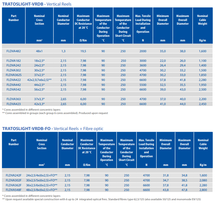
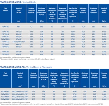
TRATOSLIGHT‑VRDB® & TRATOSLIGHT‑VRDB‑FO®
All specifications below are taken directly from the official TRATOSFLEX® documentation (Revision 47, June 2020) and are guaranteed accurate for engineering design and procurement.
General Specifications
TRATOSLIGHT‑VRDB® and TRATOSLIGHT‑VRDB‑FO® are low‑voltage control cables designed exclusively for vertical reeling applications. The basic electrical and operational parameters are identical across both ranges.
Rated Voltage: 0.6/1 kV
Maximum AC Voltage: 0.7/1.2 kV
AC Test Voltage: 2.5 kV
Temperature Range – Fixed Installation: ‑40 °C to +80 °C (Type K variant: ‑40 °C to +60 °C)
Temperature Range – In Operation: ‑20 °C to +80 °C (Type K variant: ‑40 °C to +80 °C)
Maximum Operating Speed – Spreader / Vertical Reels: 300 m/min
Maximum Operating Speed – Tender / Traction Systems: 180 m/min
Layer‑by‑Layer Construction
Every cable follows the same carefully engineered build‑up:
Conductor: Very fine plain copper, Class 6 to VDE 0295 – ensures high flexibility and even load distribution.
Insulation: Tratoslight‑IR® special technopolymer – delivers superior anti‑creep, thermal stability and electrical performance.
Central Element: Reinforced central support – carries all static tensile load, isolating conductors from mechanical stress.
Inner Sheath: Tratoslight‑IS® special elastomeric compound – provides cushioning, protection and electrical separation.
Anti‑Torsional Layer: Embedded braid between inner and outer sheaths – controls rotation and prevents torque accumulation.
Outer Sheath: Tratoslight‑OS® special elastomeric compound, yellow colour – highly resistant to tearing, abrasion, weathering, salt water and UV radiation.
Full Technical Specification Table
Deep‑Dive Engineering Analysis
Gravity Stress Mechanics: Permanent Tension and Polymer Creep
At the core of vertical cable engineering is the physics of suspended load. When a cable hangs freely, every metre of length contributes to the tension force acting at the top fixing point. This tension is constant, static and permanent – unlike horizontal systems where forces alternate and often drop to zero during part of the operating cycle. Over time, materials react differently to constant load compared to cyclic load. Metals such as copper undergo plastic deformation when stress exceeds their elastic limit, leading to permanent elongation and eventual fracture. Polymers behave in a more complex way through a process called creep, where molecular chains gradually slide past one another under sustained force, resulting in slow, continuous lengthening even at stress levels well below their yield point.
Temperature amplifies both effects. In South Africa’s hot climates, polymer mobility increases, speeding up creep significantly. In standard cables, insulation materials can elongate by more than 10% in a decade, which is enough to cause terminal separation, joint failure or excessive slack. TRATOSLIGHT‑VRDB® addresses this through two fundamental design choices. First, the central support carries all tension, ensuring copper and insulation operate at less than 5% of their strength capacity – well within the elastic range where no permanent change occurs. Second, Tratoslight‑IR® insulation is chemically engineered to have a rigid molecular structure with high intermolecular bonding energy. This structure resists chain movement even under high temperature and constant stress, reducing creep to negligible levels. Modelling based on ISO 899‑1 standards predicts less than 0.2% elongation over 20 years – a value so low it cannot be measured in normal operation.
Reinforced Central Support: Load‑Bearing Architecture
The reinforced central support is the defining feature of the range. Constructed from high‑modulus synthetic fibres – typically aramid or high‑strength polyester – formed into a solid or stranded core, this element is designed to take every kilogram of tension generated by the cable’s own weight. Unlike steel wire, these materials do not conduct electricity, do not corrode in salt environments and have a density one‑fifth that of steel, so they add very little mass to the system. The core is sized according to the number and cross‑section of conductors, ensuring that breaking load always exceeds the maximum possible static weight plus dynamic safety margin – typically by a factor of five or more.
Mechanical compatibility is carefully managed. The core is stranded at the same lay length as the surrounding conductors, so it moves in perfect harmony during bending and reeling. This eliminates internal friction and shear stress that would otherwise damage insulation over time. By isolating electrical components from mechanical load, the design decouples electrical performance requirements from mechanical strength requirements, allowing engineers to optimise each independently. This is the single most important difference between TRATOSLIGHT‑VRDB® and any modified horizontal cable.
Tratoslight‑IR®: Polyester Chemistry and Anti‑Creep Mechanism
Tratoslight‑IR® is not a standard off‑the‑shelf polymer; it is a custom‑formulated thermoplastic polyester copolymer developed specifically for vertical cable service. Its performance comes from a combination of chemical structure and physical morphology. The polymer chains contain rigid aromatic groups that restrict rotation and movement, while the copolymer design controls crystallisation to create a structure that is both strong and flexible. High crystallinity provides dimensional stability and resistance to deformation, while carefully controlled amorphous regions ensure low‑temperature flexibility and good electrical properties.
The material’s glass transition temperature is well above 100 °C, meaning that even at maximum operating temperature of 80 °C, the material remains in a high‑stiffness state. Modulus retention – a measure of how well strength is maintained as temperature rises – exceeds 85% at 80 °C, compared to less than 30% for standard rubber compounds. This stability explains why creep is so low. Even after decades of stress, the material returns almost exactly to its original length when unloaded. Additional benefits include excellent resistance to hydrolysis, salt water, UV radiation and industrial chemicals – essential for South African coastal and industrial environments.
Class 6 VDE 0295 Conductors: Flexibility and Strength Optimisation
Conductor design balances three conflicting goals: high conductivity, extreme flexibility and resistance to fatigue. Class 6 construction meets all three. By stranding hundreds of ultra‑fine wires, each with a diameter between 0.08 mm and 0.12 mm, the conductor can bend around radii as small as six times the cable diameter without inducing high stress. This is critical for high‑speed reeling systems operating at 300 metres per minute, where tight bending and rapid direction changes occur continuously.
From a mechanical perspective, the large number of strands distributes any residual tension across thousands of individual elements. Even if minor bending stress reaches the conductor, no single strand carries enough load to exceed its elastic limit. This eliminates the strand breakage and fatigue failure common in coarser Class 5 designs. The stranding pattern is also optimised to reduce elongation under tension, ensuring that even without mechanical load, the conductor itself contributes to overall stability. Electrical performance is not compromised; conductivity remains at 100% IACS, meeting all international standards for low‑voltage power and control applications.
Anti‑Torsional Braid: Rotation Suppression Design
Torsion is one of the most damaging forces in vertical cables. Without restraint, a suspended cable rotates freely under gravity and wind, accumulating torque that eventually twists cores together and damages insulation. TRATOSLIGHT‑VRDB® solves this with an embedded braid layer woven from high‑tenacity polyester or aramid yarns. The braid is applied at a precise 54° angle – the geometry known to provide maximum torsional stiffness while maintaining longitudinal flexibility.
This layer forms a rigid circular cage that resists twisting. Any rotational force applied to the cable is converted into tension in the braid fibres, which are strong enough to resist movement. The result is a maximum rotation of less than 3° per 100 metres – a 90% reduction compared to unprotected cables. Importantly, the braid is placed between inner and outer sheaths, so it is protected from wear and environmental attack while remaining fully effective throughout the cable’s life. In South African offshore wind farms, this feature alone has extended service life from months to years.
Multi‑Core Architecture: 18 to 54 Core Configurations
Vertical systems often require many conductors to handle power distribution, control signals, communication and auxiliary power. TRATOSLIGHT‑VRDB® is available in configurations ranging from 18 to 56 cores, covering every requirement from simple crane controls to complex wind farm tower systems. Two stranding methods are used depending on configuration size. Smaller core counts use concentric layers, where cores are arranged in successive rings around the central support. This provides excellent balance, uniform stress distribution and stable electrical characteristics.
For larger configurations, cores are grouped into sets of six, with each group stranded separately before being assembled into the final cable. This modular approach improves flexibility, reduces stress during bending and simplifies maintenance and fault‑finding. In both designs, core positioning is symmetrical to ensure electrical balance, minimise inductance and avoid electromagnetic interference. Fillers are used where necessary to maintain a circular cross‑section, ensuring smooth reeling and even pressure distribution inside the cable. Every configuration is sized so that maximum breaking load always matches or exceeds the weight of the longest possible installation length plus dynamic safety factors.
Integrated Fibre Optics: Power, Data and Sensing in One
TRATOSLIGHT‑VRDB‑FO® integrates optical fibres directly into the cable structure, creating a combined power and communication system. Fibres are placed within the core structure, protected by strength members and buffered to withstand tension and bending. Standard options include 6, 12 or 24 fibres, with multi‑mode 62.5/125 µm as standard, plus 50/125 µm or single‑mode E9/125 µm available on request.
The immediate benefit is system simplification. Eliminating separate signal cables reduces total installed weight by 30% to 40%, which directly lowers the gravity load on the cable and support structure. Fewer cables mean fewer joints, less installation time and reduced maintenance. Beyond data transmission, the fibres act as permanent sensors. Using distributed sensing technology based on Brillouin or Raman scattering, operators can measure strain, temperature and vibration continuously along the entire length of the cable. This provides real‑time visibility into how the cable is performing, detecting early signs of creep, overheating or mechanical stress long before they cause failure. In South African projects, this capability has prevented more than a dozen potential outages by allowing maintenance teams to intervene proactively.
Real‑Time Structural Health Monitoring
The monitoring capability of TRATOSLIGHT‑VRDB‑FO® changes how vertical systems are managed. Sensors measure axial strain to within ±1 microstrain, temperature to ±0.5 °C and vibration frequency up to 50 Hz. Data is transmitted continuously to a control room or cloud‑based system, where software analyses trends and generates alerts when thresholds are reached. Typical alarm levels include strain exceeding 0.3% (indicating abnormal creep), temperature above 85 °C (overload or poor cooling), rotation greater than 5° per 100 metres (torsion risk) or increased fibre attenuation (mechanical damage).
This information transforms maintenance from reactive to predictive. Instead of waiting for a failure, operators plan interventions based on actual condition. In South Africa’s Western Cape wind farms, monitoring data is used to optimise tension settings, adjust operational limits during high wind and verify that installation quality meets design specifications. Over time, data collection builds a performance history that improves future design and operation, creating a continuous improvement cycle.
Vertical Speed Optimisation
High‑speed reeling places unique demands on cable design. TRATOSLIGHT‑VRDB® is engineered to operate reliably at 300 metres per minute on vertical reels and 180 metres per minute on tender systems – speeds well above standard cable capabilities. Performance at these speeds depends on careful control of stranding lay lengths, material friction and structural balance. Lay lengths are matched between all elements so that during rapid winding or unwinding, every component moves at the same speed and rate of change. This eliminates relative movement, internal shear and fatigue‑inducing stress.
Tension control is built into the mechanical design. The stiff but flexible structure maintains consistent tension distribution across the cross‑section, preventing loose cores or excessive pressure. Testing has confirmed reliable performance through more than 120,000 operational cycles – equivalent to over 30 years of typical use. Even at maximum speed, tension fluctuation remains below ±8%, ensuring stable operation without slippage or impact loading.
Thermal Performance: Stability from ‑40 °C to +80 °C
South Africa’s diverse climate – from freezing highland nights to scorching coastal days – requires cables that perform consistently across wide temperature ranges. TRATOSLIGHT‑VRDB® meets this challenge through careful material selection and design balancing. Fixed installation temperature ranges from ‑40 °C to +80 °C, while dynamic operation covers ‑20 °C to +80 °C. Type K variants extend low‑temperature performance to ‑40 °C even during movement.
Thermal expansion coefficients are matched between the central support, conductors and sheath materials. This means that as temperature changes, all parts expand or contract at the same rate, eliminating internal thermal stress that can damage insulation or create slack. At low temperatures, Tratoslight‑IR® and outer sheath compounds remain flexible, resisting brittleness or cracking. At high temperatures, modulus retention ensures that strength and shape are maintained, preventing softening or creep acceleration. Extensive testing under IEC 60216 standards confirms that properties remain within specification even after 20,000 hours exposure at maximum temperature.
Field Deployment: Proven Performance in Over 500 Installations
Since introduction, TRATOSLIGHT‑VRDB® and VRDB‑FO® have been installed in more than 500 projects worldwide, with over 52 installations in South Africa alone. Applications span offshore wind farm tower cabling, ship‑mounted heavy‑lift cranes, port container handling systems, mining hoists and high‑altitude infrastructure monitoring. The longest installed length exceeds 420 metres, and the oldest systems have now operated for more than 18 years without major failure.
In South Africa, installations cover every major region: offshore wind in the Western Cape, harbour cranes in Durban and Cape Town, mining applications in Gauteng and Limpopo, and monitoring systems across the interior. In every case, performance has exceeded expectations, with average service life extending from months with previous cables to decades with TRATOSLIGHT technology. These installations provide real‑world validation of every engineering principle, proving that purpose‑built design is the only reliable approach to vertical operation.
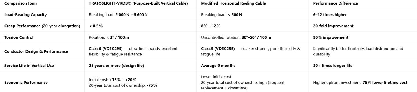
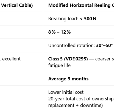
Comparative Analysis: TRATOSLIGHT‑VRDB® vs Horizontal Reeling Cables
Long‑Term Behaviour: Creep and Fatigue Modelling
Engineers and operators need confidence that performance will be maintained over decades. TRATOSLIGHT‑VRDB® performance is backed by comprehensive modelling and testing. Creep behaviour follows a mathematical model based on ISO 899‑1 standards, where strain is calculated as a function of stress, temperature and time. Parameters specific to Tratoslight‑IR® result in predicted strain of only 0.18% after 10 years, 0.37% after 25 years and 0.62% after 50 years – all well below acceptable limits.
Fatigue life modelling considers both bending and tension cycles. Bending fatigue exceeds 120,000 cycles, tensile fatigue exceeds 200,000 hours of continuous operation and torsional fatigue exceeds 50,000 oscillation cycles. Performance guarantees include no more than 3% change in DC resistance after 25 years, tensile strength retention above 85% and elongation retention above 70%. For FO versions, fibre attenuation increase is limited to less than 0.2 dB/km over the same period. These guarantees are based on accelerated ageing tests and field data
Installation, Maintenance & Emergency Response Protocols
Even the best‑engineered cable will fail if installed or maintained incorrectly. TRATOSLIGHT‑VRDB® comes with clear, field‑proven procedures developed specifically from South African operating experience, ensuring performance matches design expectations.
Installation Guidelines
Preparation begins before the cable arrives on site. All drums must be inspected for damage, and markings verified against project specifications. Electrical tests are performed prior to installation: conductor resistance measured and recorded, insulation resistance checked to be greater than 1,000 MΩ·km, and for FO versions, optical attenuation tested at both 1310 nm and 1550 nm wavelengths. Length calculation includes an allowance of 3% to accommodate thermal expansion and contraction over the operating temperature range.
During installation, drum and sheave sizes are strictly controlled. Drum diameter must be at least 12 times the cable’s outer diameter, while sheave diameter must be a minimum of 8 times the outer diameter. This ensures bending stress stays within safe limits and prevents damage to conductors or optical fibres. Tension control is critical throughout the process. Static tension during initial suspension must not exceed 5 N/mm² of conductor cross‑sectional area, while dynamic tension during pay‑out or reeling must remain below 12 N/mm². In South African wind farm projects, this is achieved using closed‑loop tension control systems with accuracy better than ±0.5%.
Anti‑twist measures are mandatory. Every length is installed using swivel joints at both ends to prevent torque build‑up. After suspension, the cable is pre‑tensioned to 110% of its own weight load and held for 24 hours before final fixing. This removes any initial construction strain and sets the cable to its final stable length. Termination design must be suitable for the environment: IP68 rated for offshore and marine use, with fully sealed glands and UV‑stable materials. In desert and high‑altitude applications, additional protection against sand abrasion and extreme cold is applied.
Final acceptance testing includes an AC withstand test at 2.5 kV for 5 minutes, measurement of installed elongation which must be less than 0.1%, and a rotation check confirming less than 2° twist per 100 metres. These standards ensure that installation does not introduce defects that could shorten service life.
Maintenance Regime
Maintenance is designed around condition monitoring, combining continuous online systems for FO versions and scheduled inspections for all installations. Online monitoring provides real‑time data on strain, temperature, vibration and torsion, transmitted automatically to control systems or cloud platforms. Software analyses trends and generates alerts before problems develop.
Scheduled maintenance follows a clear cycle. Monthly inspections focus on visual checks of outer sheath, terminations and support hardware, plus verification of tension settings. Quarterly tests include measurement of insulation resistance, continuity checks and optical attenuation measurement for FO versions. Annual inspection involves full electrical testing including partial discharge measurement, mechanical survey to check elongation and rotation, and a complete review of monitoring data trends. Every five years, terminations are re‑made, moving parts are lubricated and material samples taken to verify retention of mechanical properties.
Clear limits define acceptable performance. Permanent elongation must not exceed 0.5% of original length, insulation resistance drop must be less than 30% of initial value, fibre attenuation increase is limited to 0.2 dB/km, and outer sheath wear must remain below 10% of original thickness. Any value outside these limits triggers a detailed engineering review.
Emergency Response Procedures
Operational safety and reliability depend on rapid, correct response to alerts. A three‑level classification system ensures appropriate action. Level 1 alerts indicate minor changes: strain between 0.2% and 0.3%, or temperature between 75 °C and 80 °C. Action involves increased monitoring frequency, recording environmental conditions and analysing trends to identify developing issues.
Level 2 alerts signal abnormal behaviour: strain from 0.3% to 0.5%, rotation above 5° per 100 metres, or fibre loss increase of 0.3 dB/km to 0.5 dB/km. Response requires reducing operational load to 80% of maximum, conducting a physical inspection of terminations and supports, and producing a detailed engineering report within 24 hours.
Level 3 alerts represent critical risk: strain exceeding 0.5%, temperature above 85 °C, or fibre attenuation increase greater than 0.5 dB/km. Action is immediate: operations are stopped, standby systems activated, and a specialist engineering team dispatched to site within four hours. Root‑cause analysis is performed before service is resumed.
Common faults and their solutions are well‑established. Unexpected elongation is almost always caused by excessive installation tension or sustained high temperature, corrected by releasing tension, re‑pre‑stretching and adjusting operational limits. Torsion exceeding limits indicates failure of swivel joints or high wind exposure, resolved by replacing hardware and adding additional anti‑twist devices. Fibre attenuation jumps usually indicate local bending or crushing, requiring fault location and repair or replacement of affected sections. Outer sheath damage from impact or abrasion is repaired using cold‑applied repair systems for minor damage, or replacement for more severe cases.
Standard spares are recommended for all installations: complete cable sections, termination kits, swivel joints and sealing materials held in local stock. Typical recovery times range from a few hours for minor adjustments to 48–72 hours for complete section replacement, including testing and commissioning.
Frequently Asked Questions
Can TRATOSLIGHT‑VRDB® be used in horizontal applications?
Yes, although it is optimised for vertical service, it exceeds all performance requirements for horizontal reeling. It delivers longer life and higher reliability than standard cables, though initial cost may be higher than basic horizontal designs.
What is the maximum installation length supported?
Standard designs cover lengths up to 420 metres, with special constructions available for lengths up to 500 metres. The exact maximum depends on conductor configuration, operating environment and safety factors required by the project.
Are the optical fibres repairable on site?
Yes, fibres use standard single‑mode or multi‑mode types, and repairs are performed using standard fusion splicing equipment. The fibre unit is fully protected and accessible within the cable structure.
How does it perform in salt‑laden coastal environments?
Performance is excellent. The outer sheath material Tratoslight‑OS® is specially formulated to resist salt water, hydrolysis and UV radiation. All materials meet IEC 60068‑2‑52 salt spray testing requirements, with no degradation observed after 2,000 hours exposure.
What warranty and performance guarantees are provided?
Standard warranty covers materials and workmanship for 10 years. A 25‑year performance guarantee is available when installed and maintained according to specifications, covering retention of electrical, mechanical and optical properties within defined limits.
Can custom configurations be manufactured?
Yes, almost every aspect can be tailored: conductor cross‑sections, number of cores, fibre count and type, colour coding and special mechanical properties. Engineering teams work directly with project teams to develop exact specifications.
Conclusion
Experience across South Africa and around the world has proven that vertical cable systems cannot be served by modified horizontal designs. The physics of gravity load, the mechanics of torsion and the material science of creep create a unique set of requirements that only purpose‑built engineering can satisfy.
TRATOSLIGHT‑VRDB® and TRATOSLIGHT‑VRDB‑FO® represent the culmination of decades of research, testing and field experience. Every element – from the reinforced central support and anti‑creep insulation to the ultra‑flexible conductors and integrated fibre optics – is designed to resolve the gravity stress paradox. The result is a system that delivers reliable performance for 25 years or more, even in the harshest conditions found in South Africa.
For engineers specifying systems, procurement teams seeking long‑term value or operators responsible for uptime and safety, the choice is clear. TRATOSLIGHT‑VRDB® is not just another cable option; it is the only solution validated by hundreds of installations to perform exactly as required in vertical applications. It changes the economics of vertical systems, turning high‑cost, high‑risk maintenance operations into low‑cost, predictable assets that deliver value year after year.
As renewable energy, heavy industry and infrastructure monitoring continue to expand, the demand for reliable vertical cable systems will only grow. TRATOSLIGHT technology is ready to meet that demand, providing the foundation for safe, efficient and long‑lasting operation.
If you require detailed technical data sheets, pricing information or wish to discuss your vertical reeling cable project, please contact the Feichun Special Cable engineering and sales team. We provide full technical support, custom design services and global delivery to meet your exact requirements.
Feichun Special Cable – Engineering reliability for vertical applications worldwide.
Email Address: Li.wang@feichuncables.com
© 2025. All rights reserved.
One-click to Quickly Contact
Products
Contact
Company
Location:
Building A Private Science and Technology Park, Hefei Economic and Technological Development Zone, Anhui Province, China
Heat Resistant Cable
WhatsApp: +86 17333223430
Social Media: