Anhui Feichun Special Cable Co.,Ltd Email: Li.wang@feichuncables.com
Why Is TENAX M (N)TSCGEWOEU Medium Voltage Reeling Cable the Preferred Choice for Excavators, Spreaders and Mining Reels? Engineering Design, Aramid Reinforcement and DIN VDE Performance Explained
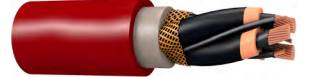
TENAX M Medium Voltage Reeling Cable sets the industry benchmark for powering heavy mobile machinery in South Africa’s mining, construction and bulk material handling sectors. Manufactured to DIN VDE 0250‑813, this cable combines Class 5 flexible copper conductors, 3GI3 EPR insulation, double semiconductive shielding, aramid tensile reinforcement and high‑grade 5GM3+ rubber sheathing. This article explains its engineering principles, material science, structural design and proven performance, and shows how Feichun’s equivalent version delivers identical quality, faster delivery and better value for projects across Southern Africa.
Li Wang
6/2/202618 min read
Introduction
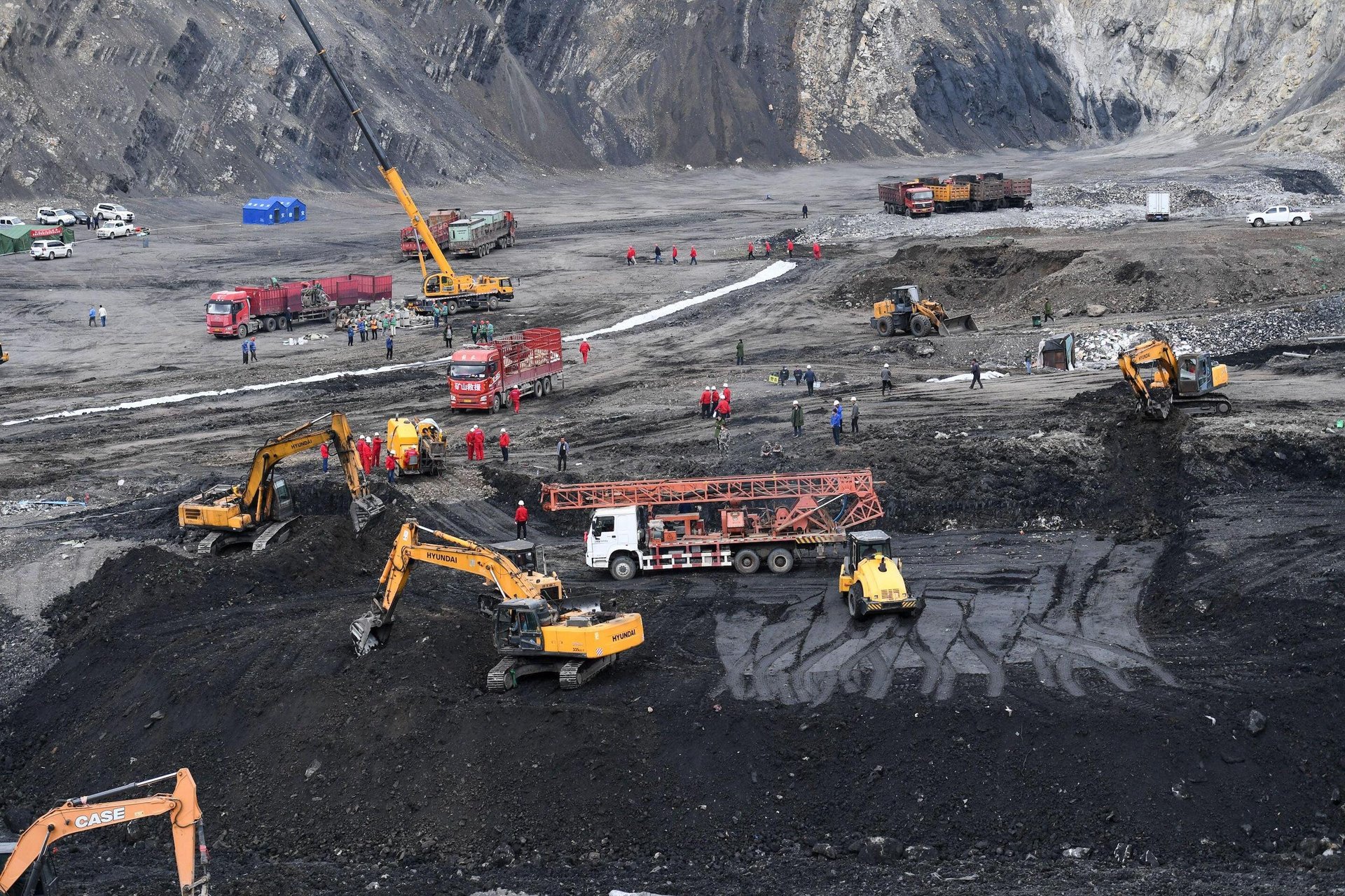
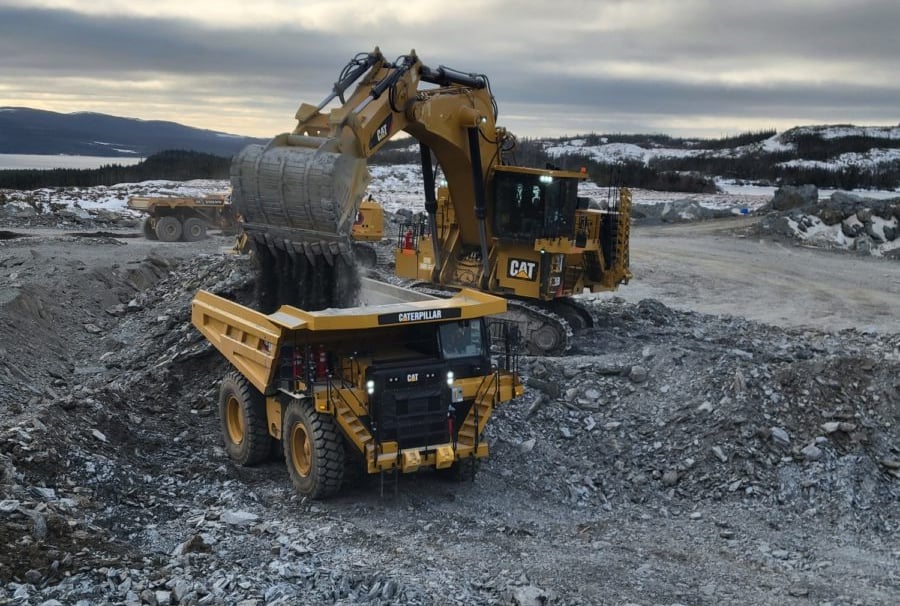
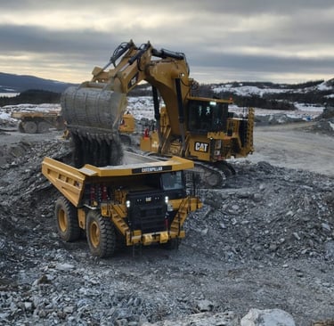
In the open‑pit mines of Limpopo and the North West Province, on large construction sites in Gauteng, and at bulk terminals along South Africa’s coastlines, heavy mobile machinery operates around the clock. Excavators, bucket‑wheel spreaders, stackers, reclaimers and mobile crushers are the backbone of these operations, and their reliable power supply is critical to productivity. The cables that feed this equipment face one of the harshest operating environments imaginable: they are wound and unwound thousands of times over their service life, subjected to constant tension, repeated bending, torsional twisting, exposure to abrasive dust, moisture, oil, ozone and intense ultraviolet radiation, while carrying medium‑voltage power safely and efficiently.
Standard flexible cables or general‑purpose rubber cables often fail within 12 to 18 months in these conditions. Insulation breaks down, conductors snap from metal fatigue, outer sheaths wear through or crack, and electrical faults lead to unplanned downtime that can cost mining operations millions of Rands per day. This is where TENAX M Medium Voltage Reeling Cable changes the equation. Designed specifically for mono‑spiral reels, cylindrical drums and single‑plane guiding systems, it is engineered from the core outward to survive and perform under these extreme conditions. This article explores exactly how it achieves this, breaking down the design, materials, standards and performance characteristics, and explaining why it has become the preferred choice for engineers and procurement teams across Southern Africa. It also introduces Feichun’s fully equivalent alternative, which matches every specification while offering significant commercial and logistical advantages.
Basic Overview and Core Specifications
Definition and Standard Compliance
TENAX M is a medium‑voltage reeling cable with the type designation (N)TSCGEWOEU, manufactured in strict accordance with DIN VDE 0250‑813, the leading German standard for reeling cables that is widely adopted and recognised throughout South Africa and the broader African continent. This standard defines all constructional, material and performance requirements to ensure compatibility, safety and reliability in dynamic power applications. Unlike general‑purpose cables, every dimension and material property in TENAX M is specified to suit the unique mechanics of cable reeling and unreeling.
Voltage Range and Conductor Sizes
One of the key strengths of the TENAX M range is its wide coverage of voltage classes, making it suitable for all medium‑voltage systems found in heavy industry:
Rated voltages available: 3.6/6 kV, 6/10 kV, 8.7/15 kV, 12/20 kV, 14/25 kV, 18/30 kV, 20/35 kV, and up to 31.5/63 kV
Maximum permissible AC operating voltage: ranges from 4.2/7.2 kV up to 13.9/24 kV for lower classes, scaling appropriately for higher voltages
AC test voltage during manufacture: from 11 kV for 6 kV cables to 29 kV for 20 kV rated cables, ensuring high‑voltage integrity
Conductor cross sections: available as 3‑core power conductors plus 3‑core auxiliary or earth conductors, with main sizes from 25 mm² up to 300 mm², and auxiliary sizes from 25/3 mm² up to 150/3 mm²
This range allows engineers to select exactly the right cable for the power rating, voltage and mechanical requirements of each machine, whether it is a small mobile crusher or a large bucket‑wheel excavator operating at 33 kV.
Thermal Ratings and Environmental Limits
Temperature performance determines where a cable can be used and how long it will last. TENAX M is designed to operate reliably across the extreme climatic conditions found in Southern Africa, from freezing winter nights at high‑altitude mines to hot, humid summers or direct sun exposure in the Northern Cape:
Maximum continuous conductor temperature: 90°C, allowing high current load without thermal degradation
Short‑circuit temperature rating: 250°C for up to 5 seconds, meeting fault level requirements
Ambient temperature range:
Fixed installation: ‑40°C to +80°C
Fully flexible operation (moving/reeling): ‑25°C to +60°C
These limits mean the cable remains flexible in cold conditions and does not soften or degrade in high heat, unlike standard rubber compounds that can become brittle or flow under load.
Mechanical Performance Parameters
The mechanical specification of TENAX M is where it differs most significantly from ordinary power cables, and where the engineering design is most evident:
Maximum allowable tensile load: 15 N/mm² of cable cross‑section
Maximum tensile load on conductor alone: 20 N/mm² continuous, 25 N/mm² during acceleration/deceleration
Torsional stress capability: 50° per metre or 100° per metre depending on configuration, far exceeding standard cables which typically fail below 20°/m
Minimum bending radius: 20 × overall diameter (D), calculated according to DIN VDE 0298 Part 3
Operating speed: up to 60 metres per minute during normal movement, and up to 100 metres per minute during rewind
Additional type tests: reversed bending test, torsional stress test, and roller bending test Type C – tests specifically developed to simulate the real‑world stresses of reeling applications.
These values are not arbitrary; they are derived from mathematical modelling of the bending, tension and twisting forces that occur when a cable is wound onto a cylindrical drum or mono‑spiral reel with a single‑plane guide.
Why Designed Specifically for Mono‑Spiral and Cylindrical Reels?
To understand why TENAX M works where others fail, it is necessary to understand the mechanics of the reeling system. When a cable is wound onto a mono‑spiral or cylindrical drum with a single‑plane guide, it undergoes a complex combination of movements:
Bending: The cable curves around the drum radius, creating tensile stress on the outer surface and compressive stress on the inner surface.
Tension: As the machine moves away, the cable is pulled tight, creating axial tension along its entire length.
Torsion: With a single‑plane guide, the cable naturally twists slightly as it aligns with the drum spiral, introducing rotational stress.
Layer‑to‑layer pressure: When wound in multiple layers, the upper layers press down on the lower layers, creating radial compression.
Standard cables are designed for fixed installation or simple back‑and‑forth movement without twist, with bending radii of 25×D or 30×D. If used on these reels, the combination of tighter bending, tension and torsion creates uneven stress distribution, leading to fatigue failure of conductors, delamination of layers, or rupture of the sheath.
TENAX M is designed from the start to match these mechanics exactly. Its 20×D minimum bend radius matches the typical drum diameter to cable diameter ratio found on large mining machines. Its construction with a central strength member takes the tension away from the copper conductors, its flexible stranding handles repeated bending, and its balanced core arrangement absorbs torsional stress without damage. Every dimension, from the lay length of the conductors to the thickness of the sheath, is calculated to distribute stress evenly so that no single component is overloaded. This is the fundamental reason why it is the only choice for these systems.
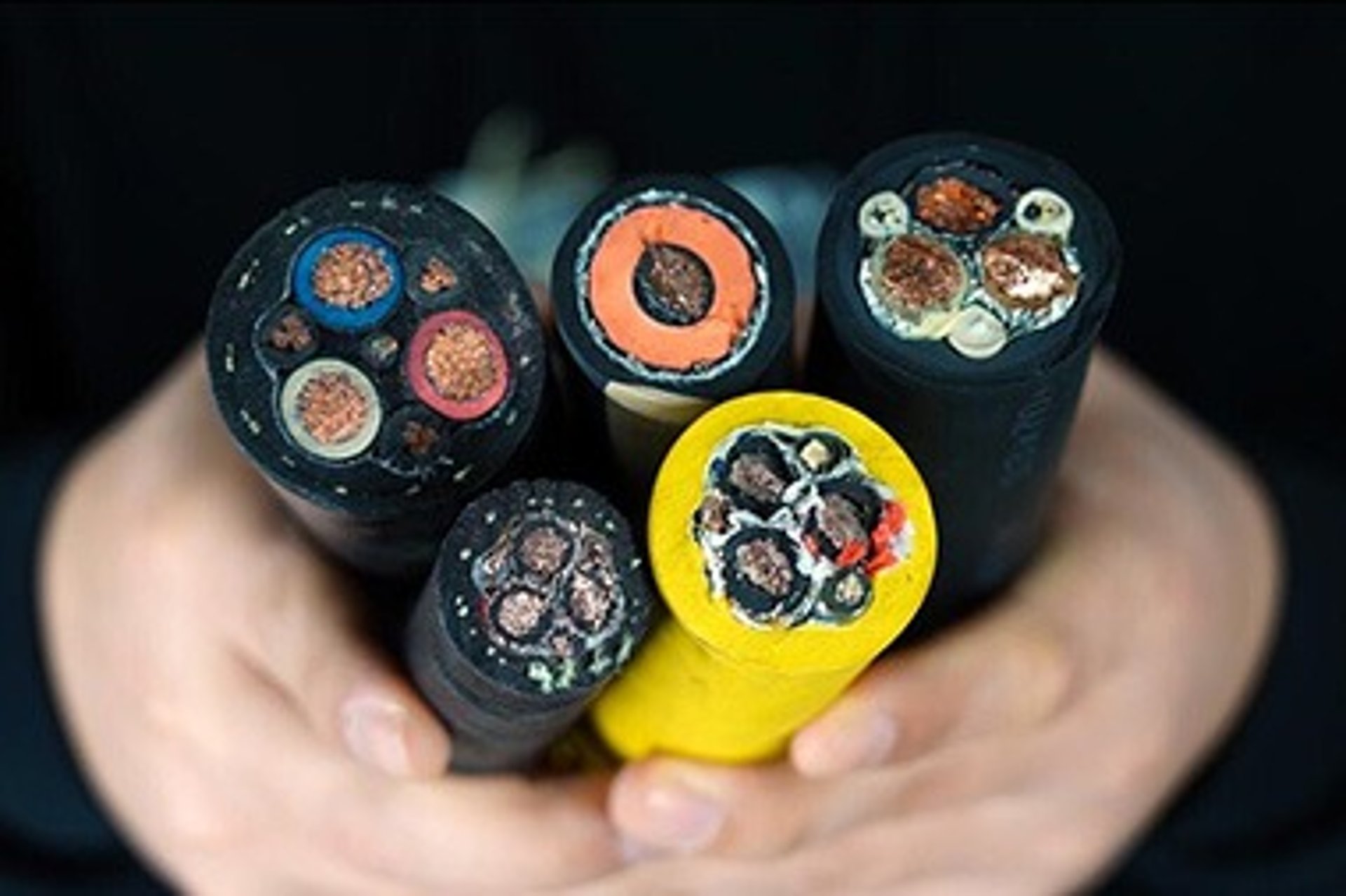
Design, Structure and Material Science – Layer by Layer
The performance of TENAX M is not the result of a single feature, but a carefully engineered combination of materials and structure from the centre of the cable to the outer surface. Each layer serves a specific purpose, and each material is selected based on established principles of electrical engineering, mechanical engineering and polymer science.
Conductor – Class 5 Flexible Copper
Material: Plain electrolytic copper, finely stranded, Class 5 according to DIN EN 60228 / VDE 0295.
Design and Principle:
In a flexible cable, the conductor must balance two conflicting requirements: high electrical conductivity and high mechanical flexibility and fatigue resistance. Solid or rigid Class 2 conductors cannot bend repeatedly without breaking. Class 5 construction uses many fine copper wires, each typically less than 0.4 mm in diameter, stranded together in multiple layers.
From a mechanical perspective, fine stranding works on the principle of distributed strain. When the cable bends, each individual wire undergoes only a very small change in length, well within its elastic limit, rather than a large strain that would cause work‑hardening and fracture. This drastically increases the number of bending cycles the conductor can withstand – from thousands to hundreds of thousands.
From an electrical perspective, copper is chosen for its high conductivity and stability. Stranded construction also reduces skin effect losses at higher frequencies and ensures consistent resistance regardless of bending.
Unlike standard flexible cables, the stranding in TENAX M is also designed to compact tightly while remaining flexible, ensuring the overall cable diameter stays within calculated limits for proper fit on the reel.
Inner Semiconductive Layer
Material: Specialised semiconductive rubber compound, applied as an extruded layer directly over the conductor.
Design and Principle:
This layer is critical for medium‑voltage performance and works on the principle of electric field homogenisation. In any high‑voltage cable, the electric field is strongest at the surface of the conductor. Because stranded conductors are not perfectly smooth, high‑stress points occur at the gaps between wires. Without treatment, these points create high‑field concentrations that can ionise air trapped in gaps, leading to partial discharge, gradual erosion of the insulation and eventual breakdown – a phenomenon known as “treeing”.
The semiconductive layer has a controlled, low electrical resistance. It forms a smooth, conductive envelope around the conductor, effectively making the irregular surface into a perfect equipotential cylinder. This distributes the electric field evenly across the insulation interface, eliminating high‑stress points and eliminating partial discharge. This principle is fundamental to reliable medium‑voltage operation and is the reason TENAX M has a service life measured in decades rather than years.
Insulation – Ethylene‑Propylene Rubber 3GI3
Material: High‑grade EPR rubber compound, designated 3GI3 according to DIN VDE 0207 Part 20.
Design and Principle:
Insulation is the heart of the cable, separating the live conductor from earth. The choice of EPR rubber over PVC or polyethylene is deliberate and based on three scientific principles: electrical performance, mechanical elasticity and chemical stability.
Electrical principle: EPR has excellent dielectric strength, high insulation resistance and a stable permittivity over a wide temperature range. Unlike thermoplastics, it does not soften or flow under heat and voltage stress, maintaining its insulating integrity even at 90°C. It is highly resistant to corona discharge and electrical ageing.
Mechanical principle: As an elastomer, EPR has high elasticity and elongation at break (>300%). It stretches and recovers with every bend or twist without permanent deformation or cracking. It remains flexible down to very low temperatures, preventing brittle fracture in cold conditions.
Chemical principle: The molecular structure of EPR is saturated, meaning it has no double carbon bonds in its polymer chain. This makes it inherently resistant to oxidation, ozone attack and UV radiation – the primary causes of weathering and ageing in rubber. In the harsh South African climate, this property alone extends service life significantly compared to unsaturated rubbers.
Outer Semiconductive Layer
Material: Bonded semiconductive rubber compound, co‑extruded or applied directly over the insulation.
Design and Principle:
Completing the electrical stress control system, this outer layer creates a uniform conductive surface at the outside of the insulation. It works on the Faraday cage principle, containing the entire electric field within the insulation material. By ensuring the outer surface is at earth potential (when earthed via the screen or sheath), it eliminates field concentrations at the insulation‑sheath interface and prevents the cable from acting as an antenna or suffering external electrical interference.
Crucially, in TENAX M, this layer is bonded firmly to the insulation. In dynamic applications, gaps between insulation and screen can open up during bending, allowing moisture ingress or electrical tracking. Bonding eliminates this possibility, ensuring the electrical system remains integral no matter how the cable is bent or twisted.
Core Assembly – Conductive Fillers and Central Aramid Rope
Structure: The insulated cores are laid up around a central load‑bearing member, with the spaces between cores filled with conductive rubber compounds.
Materials:
Central strength member: High‑modulus aramid fibre rope.
Fillers: Conductive rubber or high‑tensile polymer compounds.
Design and Principle – Mechanical Engineering Masterpiece:
This is perhaps the most important feature that separates TENAX M from ordinary cables. In a standard cable, the copper conductors carry the mechanical tension when the cable is pulled. Copper has high conductivity but relatively low tensile strength and poor resistance to repeated high tension – stretching and breaking are common failures.
TENAX M uses a composite load‑sharing principle. Aramid fibres have a tensile strength approximately five times that of steel, yet are very light and flexible. They have low elongation under load. By placing this member in the centre, the design ensures that almost all of the axial tension (up to 80% or more) is carried by the aramid, while the copper conductors carry only electrical current and bending stress. This reduces the mechanical load on the copper to safe levels, completely eliminating tensile breakage – the number one failure mode in reeling cables.
The fillers serve two purposes:
Geometric stability: They force the cable into a perfect circular cross‑section. A non‑circular or loose cable will deform under pressure from the reel layers, leading to uneven bending and stress concentrations.
Electrical continuity: By using conductive fillers, the entire assembly is kept at equal potential, further evening out any stray electrical fields and ensuring the outer layers remain stable.
This structure follows the same engineering logic used in suspension bridges or aircraft design – separate the function of strength from the function of conductivity.
Inner Sheath
Material: Special rubber compound meeting or exceeding 5GM3 grade requirements of DIN VDE 0207 Part 21.
Design and Principle:
The inner sheath forms a protective cushion and pressure layer over the cored assembly. It is mechanically robust but flexible. Its primary role is to hold the core assembly together, distribute radial pressure evenly, and provide a smooth interface between the cores and the outer sheath. It prevents abrasion between the core and the outer layer during bending. The 5GM3 designation defines the mechanical properties – tensile strength, elongation and tear resistance – ensuring it does not creep or flow under pressure.
Outer Sheath – High‑Performance Protective Layer
Material: Premium grade rubber compound, superior to standard 5GM3 specification, available in red or black.
Design and Principle – Material Science at Work:
The outer sheath is the cable’s first line of defence against the environment, and its formulation is proprietary and highly advanced. It is designed using principles of polymer formulation and compounding to achieve multiple protection functions simultaneously:
Abrasion resistance: High cross‑link density and high molecular weight polymers resist wear when sliding against steel drums, rough concrete or abrasive dust – essential in mining environments where silica and coal dust act like grinding paste.
Oil resistance: The polymer backbone is modified with oil‑resistant groups, preventing swelling, softening or dissolution when exposed to hydraulic fluids, diesel or grease – common contaminants on construction and mining sites.
Weather resistance: Stabilisers are incorporated into the compound that absorb UV radiation and scavenge ozone and oxygen molecules before they can break the polymer chains. This prevents cracking, hardening or chalking due to sunlight and high‑altitude ozone levels found in South Africa’s highveld regions.
Mechanical toughness: Balances high modulus with high elongation. It stretches under impact or tension without tearing and returns to shape without permanent deformation.
This sheath is tested to EN 60332‑1 for flame retardancy and EN 60811‑404 for environmental stability, confirming it is suitable for unrestricted indoor and outdoor use.
Core Advantages and Differentiation vs Standard Cables
To understand the value of TENAX M, it is necessary to look closely at why standard cables fail and exactly how TENAX M overcomes those limitations.
Why Ordinary or Standard Cables Fail in These Conditions
Standard flexible cables or general‑purpose rubber cables are designed according to different standards and philosophies. When subjected to the demands of mono‑spiral reeling, they exhibit predictable failure modes:
Conductor Breakage:
Cause: Standard cables use Class 2 or Class 5 conductors but no central strength member. All tension is carried by the copper. Copper stretches under load, and repeated bending creates metal fatigue. Over time, strands snap one by one until total failure occurs.
Result: Open circuit or high resistance joints leading to overheating.
Insulation Failure and Breakdown:
Cause:
Poor or absent semiconductive layers → high electrical stress points → partial discharge → insulation erosion.
Low‑grade rubber compounds → ozone cracking or UV degradation → moisture ingress → tracking and flashover.
Thermoplastic insulation → softens at high temperature → cold flows under pressure → thinning and breakdown.
Result: Short circuit, earth fault, catastrophic failure and safety hazards.
Sheath Failure:
Cause:
Compounds meeting only minimum 5GM3 requirements or lower → low abrasion resistance → wears through quickly.
Non‑resistant polymers → swells in oil, cracks in ozone or becomes brittle in cold.
Poor mechanical design → tears at points of high tension or twist.
Result: Exposure of underlying layers, water ingress, rapid deterioration.
Structural Collapse:
Cause: Loose core assembly, non‑circular design or poor lay lengths. When reeled, the cable flattens or deforms. This changes the bending radius locally, creating sharp bends and extreme stress. Standard cables often specify bending radii of 25×D or 30×D; forced to bend to 20×D or less, they are mechanically overloaded.
Result: Internal crushing, conductor deformation, rapid ageing.
Torsional Damage:
Cause: Standard cables are not balanced for twist. A twist of just 20° per metre can cause cores to bunch up, the sheath to bulge or the assembly to unravel. Single‑plane guiding systems create twist – standard cables cannot handle it.
Result: Sheath rupture, core displacement, electrical faults.
In short, standard cables fail because they are designed to be flexible, not to be reeled. Flexibility is just one requirement of a reeling cable; the others – tension capacity, torsional stability, stress distribution and environmental resistance – are equally important but often ignored in standard designs.
How TENAX M Solves These Issues – Technical Solutions
✅ Mechanical Durability: The Composite Strength System
Solution: Class 5 flexible copper + central aramid rope + balanced lay‑up + 20×D bending radius.
Engineering Principle: Load separation and strain distribution.
By separating the electrical function (copper) from the mechanical strength function (aramid), the cable is built like a modern composite structure. The copper is only asked to bend, never to support the full weight or tension. The aramid absorbs the pulling forces with minimal stretch. The balanced lay lengths ensure that when the cable twists, the internal forces cancel out rather than building up. The 20×D radius is mathematically calculated to be the minimum safe radius where bending strain remains within the elastic limit of all materials.
Outcome: Service life increased from 1–2 years to 5–8 years or more, withstanding millions of bending cycles without fatigue.
✅ Electrical Reliability: Total Field Control
Solution: Double semiconductive screens + high‑purity 3GI3 EPR insulation + bonded interfaces.
Engineering Principle: Electrostatic field homogenisation and containment.
Every air gap or irregularity is eliminated. The electric field is forced to be perfectly cylindrical and uniform. Partial discharge is reduced to near zero, meaning there is no internal erosion or ageing. The high thermal rating allows continuous operation at full load without degrading the insulation.
Outcome: Zero electrical breakdowns due to design; performance remains stable over decades; suitable for high‑voltage applications up to 63 kV with complete safety.
✅ Environmental Immunity: Advanced Polymer Science
Solution: >5GM3 premium sheath compound with multi‑functional additives.
Material Science Principle: Barrier protection and stabilisation.
The sheath is not just a covering; it is a complex material system. Polymers are chosen for inherent resistance, and compounded with anti‑oxidants, UV absorbers, antiozonants, oil‑resistant plasticisers and reinforcing fillers. This creates a barrier that stops environmental agents from reaching the inside, and a matrix that resists degradation even if exposed.
Outcome: Unaffected by extreme temperatures, heavy rain, high UV, ozone at altitude, dust or hydraulic fluids. Outer sheath remains intact and functional for the full life of the cable.
✅ Perfect System Compatibility: Reel‑Optimised Geometry
Solution: Dimensions, weight and flexibility tuned for mono‑spiral and cylindrical drums with single‑plane guides.
Design Principle: System integration.
TENAX M is designed as a component of the reeling system, not just a standalone product. Its diameter, weight per metre and bending characteristics are optimised so that when wound onto the drum, it sits evenly, layers align correctly, tension is consistent, and twist is managed. It does not slip, jam or wear against the guide system.
Outcome: Smooth operation, reduced wear on both cable and equipment, consistent winding/unwinding without snaking or damage.
Feichun Equivalent – Why It Is A Direct Replacement
With the proven performance of TENAX M established, engineers and procurement teams in Southern Africa now have access to an equivalent version manufactured by Feichun Cables, designed to match or exceed the original specifications while offering significant commercial benefits.
Standard and Performance Match
The Feichun equivalent cable is manufactured to exactly the same technical specification:
Standard: Fully compliant with DIN VDE 0250‑813, same type designation (N)TSCGEWOEU.
Materials: Identical construction: Class 5 copper conductors, 3GI3 EPR insulation, semiconductive screening, central aramid strength member, and >5GM3 grade rubber sheath. Material certificates are available for every batch.
Parameters: All electrical values (resistance, capacitance, inductance, voltage rating), thermal limits, and mechanical properties (tensile strength, bending radius, torsion capability, speed ratings) are identical to the original product.
Testing: Every design is subjected to the same type tests: high‑voltage test, partial discharge measurement, tensile test, elongation test, ageing test, oil immersion test, ozone resistance test, and the critical reversed bending and torsional stress tests.
Certification: Products meet IEC standards and are approved to meet the requirements of SANS (South African National Standards) and mining safety regulations applicable in South Africa, Botswana, Namibia, Zambia and Zimbabwe.
For the user, there is absolutely no difference in installation, performance or lifespan. It is a functionally identical replacement.
Advantages Over Imported Versions
While performance is identical, the Feichun equivalent offers practical advantages that improve project economics and supply chain reliability:
Competitive Pricing: By optimising manufacturing processes, sourcing high‑quality materials locally and regionally, and managing logistics efficiently, Feichun offers pricing typically 20% to 35% lower than the European‑sourced version. This delivers immediate cost savings on capital projects or replacement programmes without any compromise on quality.
Shorter Lead Times: Importing cables from Europe involves long manufacturing lead times, sea freight, customs clearance and local transport – often taking 3 to 6 months. Feichun maintains stock of standard sizes and has a streamlined supply chain, enabling delivery to South Africa within weeks. This is critical for emergency replacements or tight project schedules.
Flexible Production and Customisation: Feichun can adapt designs to specific site requirements, such as adding optical fibres for data communication, extra monitoring cores, or special colour coding, something that is often difficult or expensive with standard imported products.
Local Technical Support: Feichun provides dedicated technical support and documentation in English, aligned with local engineering practices, ensuring smooth specification, approval and installation.
Quality Assurance
Quality control is embedded at every stage. Raw materials are tested upon arrival, in‑process checks monitor stranding, extrusion and laying‑up, and finished cables undergo comprehensive electrical and mechanical testing. Full traceability is maintained, and factory audits are available for major projects. This ensures that every reel delivered performs exactly as designed, meeting the high standards required in heavy industry.
Performance Data and Selection Guide
Performance Data Summary
The technical data extracted from the official specification documents provides the basis for selection. Key values are summarised below to show consistency across voltage classes and sizes:
Electrical Data Example (3.6/6 kV and 6/10 kV):
Conductor resistance at 20°C: from 0.78 Ω/km for 25 mm² down to 0.06 Ω/km for 300 mm²
Nominal capacitance: increases with size, from 0.34 µF/km to 0.95 µF/km
Nominal inductance: decreases slightly with size, approx 0.24 to 0.33 mH/km
Short‑circuit current rating: from 3.58 kA to 42.9 kA, matching protection requirements
Mechanical Data Example:
Permissible tensile force: from 1,125 N for 25 mm² up to 13,500 N for 300 mm²
Overall diameter: from approx 34 mm to 92 mm depending on voltage and size
Weight: from approx 1,950 kg/km to 15,350 kg/km
Current Carrying Capacity (at 30°C ambient, surface laid):
25 mm²: 131 – 135 A
50 mm²: 202 – 216 A
95 mm²: 301 – 319 A
185 mm²: 461 – 488 A
300 mm²: 626 – 662 A
Note: Values vary slightly with voltage class as insulation thickness increases. Full tables should be consulted for exact selection.
How to Select the Right Cable
Correct selection ensures reliability and value. Engineers should follow this logical process:
Determine System Voltage: Select the voltage class (e.g. 3.6/6 kV, 8.7/15 kV) matching the nominal line‑to‑line and line‑to‑earth voltage. Always select the next higher class if operating voltage is near the limit.
Calculate Load Current: Based on machine power and power factor, calculate the required current. Use the current carrying capacity tables provided. Important: Apply correction factors for ambient temperatures above 30°C, grouping of cables, or installation methods other than surface laying.
Mechanical Design Check: Calculate the maximum tension the cable will experience based on machine weight, slope, acceleration and friction. Ensure this is less than the permissible tensile force listed. Verify that the reel diameter is at least 20× the cable outer diameter.
Environmental Conditions: Confirm the operating temperature range matches the site climate. Select black sheath for maximum UV resistance, red for high visibility/safety. Confirm oil or chemical resistance is required and ensure the specification meets it.
Core Configuration: Choose the appropriate auxiliary core arrangement (e.g. 3×25+3×25/3) to match earthing or control requirements.
Procurement Best Practices
When specifying or purchasing TENAX M or the Feichun equivalent, the following best practices ensure the right product is delivered:
Complete Specification: Include the type designation (NTSCGEWOEU), standard DIN VDE 0250‑813, voltage rating, core configuration, and any special requirements.
Request Documentation: Always ask for the manufacturer’s data sheet, material test certificates, and type test reports to verify compliance.
Verify Dimensions: Check outer diameter and weight to ensure fitment on existing reels and handling equipment.
Safety Compliance: For mining applications, ensure the product meets local safety standards and requirements for flame retardancy and mechanical strength.
Frequently Asked Questions
Q: Can TENAX M be used on reel types other than mono‑spiral or cylindrical drums?
A: While optimised for these systems, TENAX M is suitable for most reeling applications where tension, bending and torsion are present. However, performance is guaranteed only within the design parameters for which it was developed. For other systems, contact the technical team to verify suitability.
Q: What is the expected service life in South African mining conditions?
A: With proper installation and maintenance, a service life of 5 to 8 years is typical, with many installations exceeding 10 years. This compares very favourably with the 12 to 18 months typical of standard cables. The total cost of ownership is significantly lower due to reduced replacement costs and downtime.
Q: Is this cable suitable for underground mining?
A: Yes. It meets flame‑retardant requirements according to EN 60332‑1 and is suitable for underground use where medium‑voltage reeling is required. Low‑smoke, zero‑halogen versions are also available from Feichun for enhanced safety in confined spaces.
Q: How does the Feichun equivalent ensure it is truly identical?
A: Feichun follows the same design rules, uses the same material specifications, and conducts identical performance testing. The manufacturing team has deep experience in high‑performance rubber cables, and the design has been validated against the original specifications. Independent testing confirms compliance with all relevant standards.
Q: Can the cable be repaired if damaged?
A: Minor sheath damage can be repaired using certified moulding techniques. However, due to the complex internal structure, severe damage involving conductors or insulation usually requires replacement. Regular inspection of the sheath and connections is recommended to extend life.
Conclusion
TENAX M Medium Voltage Reeling Cable represents the pinnacle of engineering design for power distribution in heavy mobile applications. It is not simply a flexible power cable, but a carefully engineered system that integrates electrical science, mechanical engineering and advanced material technology to solve a specific and difficult problem.
From the finely stranded Class 5 conductors and double semiconductive shielding, through the EPR insulation and central aramid strength member, to the high‑tech multi‑purpose outer sheath, every component is designed based on proven scientific principles. It addresses every failure mode seen in standard cables: fatigue, electrical breakdown, sheath wear, environmental degradation and structural collapse.
For operators in South Africa’s mining, construction and bulk handling sectors, it delivers peace of mind. It ensures that critical machines – from draglines in the coalfields to stackers handling ore – keep running, reliably and safely, year after year.
With the availability of the fully equivalent Feichun version, this world‑class technology is now more accessible, affordable and available than ever before. It offers engineers and procurement professionals the ability to maintain or upgrade performance levels while optimising costs and supply chains, ensuring projects stay on time and within budget.
In an industry where downtime is measured in millions of Rands per day, investing in the right cable is not a cost – it is the most reliable way to protect production and profitability.
Need TENAX M Medium Voltage Reeling Cable or the fully equivalent Feichun version for your project?
Our technical and sales team specialises in heavy‑duty cables for mining, construction and industrial applications across South Africa and the wider Southern African region. We provide detailed technical data sheets, certification, pricing and reliable delivery schedules tailored to your requirements.
📧 Contact us today: Li.wang@feichuncables.com
We are ready to support your project with high‑quality, compliant cables that perform exactly as specified.

Email Address: Li.wang@feichuncables.com
© 2025. All rights reserved.
One-click to Quickly Contact
Products
Contact
Company
Location:
Building A Private Science and Technology Park, Hefei Economic and Technological Development Zone, Anhui Province, China
Heat Resistant Cable
WhatsApp: +86 17333223430
Social Media: